Cir = 1 is a rough guideline to reduce mouth reflections, the impact on the response depends on the driver (actually the impedance matching 🙂 so I have to touch upon that). Mouth reflections create ripples in the throat impedance, which is responsible for the ripple in the power response: as the resistive part of the throat impedance goes up and down, the amount of power that is delivered to the air varies as well. The purpose of the driver impedance matching is to make this variation as small as possible. It is explained in this patent by Albert Thuras, and there's also some more info in the paper I posted here (also available from my website together with other papers.)
The variation in the level of reflections is not very rapid around Cir = 1, so reducing it somewhat doesn't change the response that much. Going down to 0.8 or 0.7 doesn't do that much, especially if the driver is well matched to the horn.
(A note on Cir: it is actually derived for Ang = 2pi, but it is usually taken allow for a Ang = 4pi horn to have a mouth circumference of one wavelength. I think this applies to Hornresp as well. This is also often cited as the "optimum" mouth size, due to a paper by Don Keele where he used a simple plane wave horn model and found reflections to be minimum for Cir ~= 1. However, this is due to the use of a plane wave model, and using more accurate models (like I have done in the appendix of my PhD thesis), we see that there is no optimum mouth size. Reflections are reduced as the mouth size increases.)
It looks like your design comes directly from the Hornresp design tool, which is again based in W. Marshall Leach's equations. In the paper linked to above, I investigated this quite thoroughly, and came up with some alternative methods and modifications. For instance, Leach's equations result in a reduced Vrc as T is reduced, which is correct for reactance anulling at the cutoff frequency, but performance above cutoff is not optimal. By making Vrc larger for smaller T values, the response is improved over a wider range. Also Leach's method specifies the corner frequencies, and the impedance matching is at the mercy of the upper corner frequency, while I think it's often better to design it the other way around, as this allows you more freedom in reducing the size of the horn.
Ang = 2pi corresponds to a horn flush mounted in an infinite wall, or (ignoring diffraction effects) out on a big field. The usual logic is to reduce Ang as the horn is moved closer to boundaries. But this only applies to horns flush mounted in a wall and squeezed into the corner. When you have a distance between the horn and its mirror image(s), phase shifts may cause worse mouth reflections that when the horn is far away from the walls/floor. I have done some modelling of this (see this paper), but modelling what happens due to the rear wall is harder since it includes diffraction around the horn.
If you have the space, I would err on the conservative side. If you design a horn/driver combination that has smooth response with Ang = 2, you stand a better chance of having a smooth response with out-of-phase wall reflections.
As for your design, here are a couple of tweaks you could try:
Hope this helps 🙂
The variation in the level of reflections is not very rapid around Cir = 1, so reducing it somewhat doesn't change the response that much. Going down to 0.8 or 0.7 doesn't do that much, especially if the driver is well matched to the horn.
(A note on Cir: it is actually derived for Ang = 2pi, but it is usually taken allow for a Ang = 4pi horn to have a mouth circumference of one wavelength. I think this applies to Hornresp as well. This is also often cited as the "optimum" mouth size, due to a paper by Don Keele where he used a simple plane wave horn model and found reflections to be minimum for Cir ~= 1. However, this is due to the use of a plane wave model, and using more accurate models (like I have done in the appendix of my PhD thesis), we see that there is no optimum mouth size. Reflections are reduced as the mouth size increases.)
It looks like your design comes directly from the Hornresp design tool, which is again based in W. Marshall Leach's equations. In the paper linked to above, I investigated this quite thoroughly, and came up with some alternative methods and modifications. For instance, Leach's equations result in a reduced Vrc as T is reduced, which is correct for reactance anulling at the cutoff frequency, but performance above cutoff is not optimal. By making Vrc larger for smaller T values, the response is improved over a wider range. Also Leach's method specifies the corner frequencies, and the impedance matching is at the mercy of the upper corner frequency, while I think it's often better to design it the other way around, as this allows you more freedom in reducing the size of the horn.
Ang = 2pi corresponds to a horn flush mounted in an infinite wall, or (ignoring diffraction effects) out on a big field. The usual logic is to reduce Ang as the horn is moved closer to boundaries. But this only applies to horns flush mounted in a wall and squeezed into the corner. When you have a distance between the horn and its mirror image(s), phase shifts may cause worse mouth reflections that when the horn is far away from the walls/floor. I have done some modelling of this (see this paper), but modelling what happens due to the rear wall is harder since it includes diffraction around the horn.
If you have the space, I would err on the conservative side. If you design a horn/driver combination that has smooth response with Ang = 2, you stand a better chance of having a smooth response with out-of-phase wall reflections.
As for your design, here are a couple of tweaks you could try:
- Double the throat area. This will provide impedance matching. Adjust the length to keep the cutoff frequency.
- Adjust Vrc to adjust the response near cutoff. A more rounded response will give less rapid phase shifts. If you intend to cross above cutoff, you may adjust Vrc for the best phase response/group delay, rather than the flattest/most extended response.
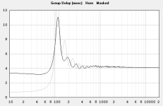
- Keep an eye on the group delay and the Futtrup limit curve. We are less sensitive to group delay at lower frequencies, so crossing one octave above cutoff is probably quite conservative for a midbass horn.
Hope this helps 🙂

I think this applies to Hornresp as well.
Just confirming that the Hornresp Cir value is indeed referenced to 4 x Pi free space. This gives an acceptable compromise between horn mouth size and the magnitude of the ripples in the throat acoustical impedance. If referenced to 2 x Pi half space, for the same cutoff frequency the mouth area would need to be twice as large to achieve a similar Cir value.
The Cir value is just a guideline indicator, and the horn mouth size can of course be set to any value that the user chooses.
With regards to back chamber volume...in the mid bass horn I proposed on previous page, hornresp suggested an optimal Vrc which was smaller than what would be required for the driver to fit into.
I adjusted the volume so the driver would fit into the chamber and this resulted in a "still ok" but less linear response.
One solution to maintain the small volume suggested by horn resp would be to design a shorter chamber with the magnet of the driver sticking out, but not sure this is a viable option.
As I write I also wonder if Vrc is the volume of the chamber + the volume of driver (cone + magnet).
So, if supposedly my driver (magnet + cone) occupies a volume of 1liter, a Vrc of 1 liter means I have to design an enclosure of 2 liters.
On such small volumes this makes a big difference.
I found driver box volume tuning useful.
I used expanding foam (have to be very careful with it), safely contained by baking parchment and Clingfilm, can really cut volume down.
I'd used sand bags before - very heavy.
The foam was then trimmed to give the volume reduction required.
I in-room measured my way forward.
Here it is before it fully expanded.
Attachments

Hello David,
Really appreciate your prompt reply.
Another question popped up in regard to Atc, I understand in low frequency we can assume it's related to Sd as the driver is working as a piston. What about high-frequency (assuming the cone is still working as a piston), can I understand Atc to be the "Area of the source of sound" or "combined total Area of sound source" which is not the driver cone area anymore.
I'm designing a micro speaker with a horn, the front rectangular chamber is small with 2 slots coming out at opposite ends (combine area = S1) with a fixed Vtc I input a much smaller Atc than Sd/S1 and I can see a rise in higher frequency, so I'm hoping to have a better understanding of Atc, thanks for your help.
Regards,
GQZ
Thank you to David and Speedysteeve for chiming on the subject.
I was planning to open a separate thread to keep this one uncluttered, but since I see more users other than Kobrek commenting on the subject, I am posting my reply here.
David, since I assume you are the "keeper" of this thread (which is about your wonderful piece of software, and not my horn), please let me know if you believe it would be more appropriate to move this discussion to a specific thread.
I remodeled the horn based on the "tweaks" that Kobrek suggested.
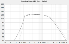
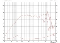
I doubled the throat and adjusted Vrc to realign the low upper cutoff corner and smoothen the ripples. The power response is as good or better than the previous simulation with the smaller throat.
However, adjusting the lenght did not result in relevant variations, at least with regard to the power response.
Making the horn shorter resulted in a higher, 150ish cutoff (bad ?) and a higher Cir (good). Making it longer caused bigger ripples (which could probably be fixed by a larger Vrc), and an even smaller Cir (0.6x) which appears to be too low.
Since the response is good enough with the previous lenght of 140cm i kept this value, also to keep Cir within 0,7 as suggested by Kolbrek. I can of course make the horn shorter if this is necessary for impedance matching and if the higher cutoff doesn't influence too much the phase shift at crossover point.
@ Kobrek I am not sure what you mean by "impedance matching". Matching the impedance curve of the driver to the horn (acoustical or electrical ?) impedance ?
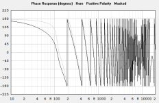
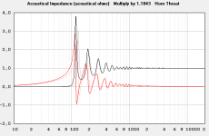
Attached below the whole set of diagrams for the "140/2800 - big throat" compared to the previous "140/2800" I also attach the impedance curve of the driver.
With regard to the driver, as I think I mentioned in a previous post, the only reason why I used this driver (Celestion TF0510) is because it results in a much smoother and extended power response than all the others I tried in hornresp, that is the whole B&C, Faital Pro, Beyma and Celestion product range (5-6" midrange). If you believe there are more drivers that would be worth trying and that may offer a better result, I will run more simulations.
In the attached diagrams the bold pattern is the new "big throat" horn. Mouth size is the same (2800) as I would not exceed the 70x40cm dimension.
With regards to group delay, I am trying to keep it at/below 5ms at 200Hz, since that seems to be the threshold of audibility of the human hearing at 300hz, according to the more recent studies published on the www.
I was planning to open a separate thread to keep this one uncluttered, but since I see more users other than Kobrek commenting on the subject, I am posting my reply here.
David, since I assume you are the "keeper" of this thread (which is about your wonderful piece of software, and not my horn), please let me know if you believe it would be more appropriate to move this discussion to a specific thread.
I remodeled the horn based on the "tweaks" that Kobrek suggested.
I doubled the throat and adjusted Vrc to realign the low upper cutoff corner and smoothen the ripples. The power response is as good or better than the previous simulation with the smaller throat.
However, adjusting the lenght did not result in relevant variations, at least with regard to the power response.
Making the horn shorter resulted in a higher, 150ish cutoff (bad ?) and a higher Cir (good). Making it longer caused bigger ripples (which could probably be fixed by a larger Vrc), and an even smaller Cir (0.6x) which appears to be too low.
Since the response is good enough with the previous lenght of 140cm i kept this value, also to keep Cir within 0,7 as suggested by Kolbrek. I can of course make the horn shorter if this is necessary for impedance matching and if the higher cutoff doesn't influence too much the phase shift at crossover point.
@ Kobrek I am not sure what you mean by "impedance matching". Matching the impedance curve of the driver to the horn (acoustical or electrical ?) impedance ?
Attached below the whole set of diagrams for the "140/2800 - big throat" compared to the previous "140/2800" I also attach the impedance curve of the driver.
With regard to the driver, as I think I mentioned in a previous post, the only reason why I used this driver (Celestion TF0510) is because it results in a much smoother and extended power response than all the others I tried in hornresp, that is the whole B&C, Faital Pro, Beyma and Celestion product range (5-6" midrange). If you believe there are more drivers that would be worth trying and that may offer a better result, I will run more simulations.
In the attached diagrams the bold pattern is the new "big throat" horn. Mouth size is the same (2800) as I would not exceed the 70x40cm dimension.
With regards to group delay, I am trying to keep it at/below 5ms at 200Hz, since that seems to be the threshold of audibility of the human hearing at 300hz, according to the more recent studies published on the www.
Attachments


Another question popped up in regard to Atc
Hornresp models the throat chamber as a cylinder of length Ltc, cross-sectional area Atc and volume Vtc (Atc x Ltc) The typically used setting for Atc is Sd x number of drivers.
For a given Vtc, the value of Atc is sometimes adjusted to make the value of Ltc better match the actual physical design of the system. It is really a judgement call on the part of the user to decide what values to specify for the throat chamber to best reflect the design.
Moving the mouse pointer over the Atc input box shows the value of Ltc for a given Vtc and Atc in the status bar panel at the bottom of the Input Parameters window.
If the 'chamber resonances masked' option is selected then the throat chamber is treated as a pure acoustic compliance and the results will be dependent on the value of Vtc only - it doesn't matter what value is used for Atc (or Ltc).
can I understand Atc to be the "Area of the source of sound" or "combined total Area of sound source"
Strictly speaking, and certainly as far as the Hornresp model is concerned, the "area of the source of sound" remains as Sd x number of drivers, regardless of the values chosen for Atc and S1.
please let me know if you believe it would be more appropriate to move this discussion to a specific thread.
Thanks for asking, but moving is not necessary 🙂.
@ Kobrek I am not sure what you mean by "impedance matching". Matching the impedance curve of the driver to the horn (acoustical or electrical ?) impedance ?
I understand this concept can be a bit confusing and unfamiliar, since usually when we talk about impedance in connection with loudspeakers, we mean electrical impedance. But there is also mechanical impedance and electrical impedance, and it is possible to draw an equivalent schematic that combines electrical, mechanical and acoustical parts as simple components. The first paper I linked to shows this schematic.Then you can use the Thévenin theorem to simplify a circuit into a source with an internal impedance Zs that drives a load impedance ZL.
It can be shown that the condition that results in maximum power in ZL is Zs = ZL. Also, if ZL varies, the variation is the least around Zs = ZL.
For a horn loudspeaker, ZL is the acoustic throat impedance of the horn. Zs is made up from the mechanical and electrical impedances of the driver. While there is a connection between Zs, ZL and the electrical impedance at the driver terminals, the connection is not straightforward, and you can't use the electrical impedance to check impedance matching. Also, since the horn throat impedance varies quite a lot, the best we can do is to match the driver to the average of the throat impedance over a given frequency range. This is done by adjusting the Sd/St ratio in relation to BL and Re. The easiest is actually to use the equations for impedance matching from my blog. There's also a book 🙂
But there is also mechanical impedance and electrical impedance,
Just to clarify - I am pretty sure that Bjørn meant to say: "But there is also mechanical impedance and acoustical impedance," 🙂.
WelI, I tried to study those papers but had to give up because they are far beyond my comprehension and knowledge of mathematics. Looks like Arab language to me, and I'm not an Arab (smile).
Also I don't have a clue how to even measure the mechanical impedance of a driver.
I wonder if all that math is absolutely needed/required - in which case I guess I will have to give up the project - or if the horn can be designed in a fashion that will not require solving equations, and still yield good results. I mean, not as good but still "good enough".
The papers also cover a lot more than impedance matching, so don't worry. I also wrote this for people who want to dig a bit deeper.
You don't need to measure the mechanical impedance. It's not easy to do anyway. The values you need can be calculated from the driver parameters. With a fixed driver, you only need to calculate the throat area, as the rear chamber volume is best adjusted manually. So in this case, the only equation you need is:
S1 = Re/BL^2 * Sd^2 * 0.0415
Re, BL and Sd come from the driver datasheet, Sd and S1 will be in square centimeters. All you need to do is to plug the driver parameters into the formula. You can check that against your design, S1 should come out at 34.78cm2. (This is not solving an equation, it is applying a formula 🙂 )
I agree that is not an equation 😀 and I did not realize that in suggesting to double the size of the throat you had already considered that calculation based on the driver's parameters.
So I assume that is supposed to be the "starting point" for any horn model, while the rest of the data (horn mouth. lenght, VRC etc. can more or less be adjusted in order to obtain a flat response in the power response window.
In this case, can electrical and acoustical impedance diagrams be disregarded as the matter has already been taken care of in a different, more specific manner ?
And is there anything else that would require further optimization before I purchase the drivers and start the woodworking ? What about delay and phase ?
PS.
More in general but still with regards to TS parameters....how is one supposed to go about modeling a Mid or High frequency horn based on a compression driver, since for those no TS parameters are available ? Nor they can be measured with REW or DATS since it impossible to add a weight to the cone as it is done with cone speakers.
I don't believe you can model compression drivers.
Stick with lowest usable freq as at least double the cutoff freq, only cover 3 octaves range, and you'll not go far wrong.
Choose your profile poison 🙂
Conicals directive and pointy, tractrix nice in mid range, Le Cléac'h great for higher frequencies.
Unless you have a huge room, use of Le Cléac'h for deeper frequencies is prohibited by the sheer size of them.
I use Exponential for mid bass, tractrix for mids, Le Cléac'h for upper mid and then tweeter of choice.
Integrates really well.
Still every horn sounds quite different. Based on what you say it may have more to do with the how the profile develops than actual interaction with the drivers though.
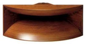
I really love old Altec muticellulars and TAD style "exponentials" (probably not "really" exponentials) for mid highs 1 to 5k-ish, , as well as the JBL "butt cheecks" biradials both for midhighs and highs. I'm not a fan of bullet tweeters, possibly due to the directivity vs biradials.
It would be interesting to understand more about the curved mouth profile of those horns, how it impacts on the response and if it can be considered as a way to improve the mouth surface 10-15% without making the horn actually larger.
I believe the dispersion figures must be at the base of the beatiful broad soundstage and pinpoint imaging of those horns, which I find somewhat missing in other profiles. Especially in rooms which are not heavily treated, so I guess it MUST have to do with dispersion.
Attachments

I don't believe you can model compression drivers.
Jean-Michel Le Cléac'h used the following parameter values to model a TAD TD2001 compression driver in Hornresp:
Sd = 18.10
Bl = 7.20
Cms = 1.60E-04
Rms = 2.72
Mmd = 1.60
Le = 0.06
Re = 6.30
Vrc = 0.14
Lrc = 2.70
Fr = 40000
Tal = 1.00
Vtc = 0.81
Atc = 18.10
how is one supposed to go about modeling a Mid or High frequency horn based on a compression driver, since for those no TS parameters are available ?
If driver parameter values are not available then use the constant diaphragm velocity (Vel) option.
(Double-click the Eg label in Edit mode to select the Vel option).
Ah yes, I forgotten that.Jean-Michel Le Cléac'h used the following parameter values to model a TAD TD2001 compression driver in Hornresp:
Sd = 18.10
Bl = 7.20
Cms = 1.60E-04
Rms = 2.72
Mmd = 1.60
Le = 0.06
Re = 6.30
Vrc = 0.14
Lrc = 2.70
Fr = 40000
Tal = 1.00
Vtc = 0.81
Atc = 18.10
Where did those come from?
Best fit against measured outputs, perhaps across a range of horn profiles?
I don't know how Jean-Michel arrived at the values, but he certainly seemed to think that they were reasonably accurate, and used them when simulating his Le Cléac'h horn designs in Hornresp.
Hornresp Update 5460-230501
CHANGE 1
The functionality of the compression ratio calculation feature has been refined to more correctly take into account stepped segment designs. Previously with offset drivers the mouth area of segment 1 was used in the calculations, now the throat area of segment 2 is used instead.

CHANGE 2
The compression ratio message now includes the number of drivers. The message for a front loaded horn system with 2 drivers for example, now shows 2 x Sd / S1 rather than just Sd / S1. The calculated compression ratio value itself has not changed.

CHANGE 3
Minor amendments have been made to the Input Parameters Window section of the Help File to take into account recent update changes.
Kind regards,
David
CHANGE 1
The functionality of the compression ratio calculation feature has been refined to more correctly take into account stepped segment designs. Previously with offset drivers the mouth area of segment 1 was used in the calculations, now the throat area of segment 2 is used instead.
CHANGE 2
The compression ratio message now includes the number of drivers. The message for a front loaded horn system with 2 drivers for example, now shows 2 x Sd / S1 rather than just Sd / S1. The calculated compression ratio value itself has not changed.
CHANGE 3
Minor amendments have been made to the Input Parameters Window section of the Help File to take into account recent update changes.
Kind regards,
David
- Home
- Loudspeakers
- Subwoofers
- Hornresp