Thanks for the clarification David. Unfortunately the horn loudspeaker wizard is greyed out on my horn and can't be selected. I already had an idea of the curve from reading the more updated study on the subject, and although it would be great to have it superimposed on my GD graphics, it is still possible to make an evaluation of where my GD curve is in relation to Futrupp's.
So far I have considered the group delay figures only at the intended crossover point.
In other words with a xover at 200Hz I have tried to keep the GD below 4.5ms at 200Hz, disregarding what happens at higher frequencies, basically for two reasons:
1) above xover point (depending of course on Xover slope) a given signal is reproduced only by one driver, and for this reason there is no audible delay between the two signals reproduced by two drivers at Xover point and around it.
2) Lower GD values can be compensated by phisical realignment of the two drivers/horns involved. For example 1ms = about 34cm which can be reduced to 17cm if one takes advantage of a 180 phase shift.
That being said after reading the Futrupp paper linked by Kolbrek I am no longer so sure that these assumptions are correct,
Which would be a problem because as far as I can see there is no easy way to model a bass/midbass horn with a very short lenght = small GD value.
PS.
Of course this is not taking into consideration the possibility to adjust delay through passive crossovers or DSP.
It's simple - just read the Help file 🙂.More things in Hornresp that I didn't even know about! How will I ever keep up!

If you are using a single segment exponential horn for your simulations, add a very short cylindrical segment before the main segment to make it a multiple segment horn - the Loudspeaker Wizard can then be used.Unfortunately the horn loudspeaker wizard is greyed out on my horn and can't be selected.
For example, if the single segment horn has:
S1 = 100
S2 = 3000
L12(Exp) = 100
Then specify the multiple segment horn as:
S1 = 100
S2 = 100
S3 = 3000
L12(Exp) = 0.01
L23(Exp) = 100
Hornresp Update 5460-230508
How to DL? The link has disappeared and I'm having some strange issues with the basic TH driver option
Hi GM,
The Hornresp download link is http://www.hornresp.net
Is it possible to provide further information on the TH issues you are experiencing?
Kind regards,
David
The Hornresp download link is http://www.hornresp.net
Is it possible to provide further information on the TH issues you are experiencing?
Kind regards,
David
Group delay has two parts: the linear phase part, which is only a pure propagation time delay (basically a vertical offset of the whole group delay curve) and the access group delay, which comes from rapid phase shifts. It's the last part you should compare to Futtrup's curve. I'm not sure if Hornresp can do the required offset? In David's example about 4ms seems to be the propagation delay. The group delay curve will typically flatten out to become very close to the propagation delay at high frequencies (with occasional artifacts from rear chamber standing waves etc).So far I have considered the group delay figures only at the intended crossover point.
In other words with a xover at 200Hz I have tried to keep the GD below 4.5ms at 200Hz, disregarding what happens at higher frequencies, basically for two reasons:
1) above xover point (depending of course on Xover slope) a given signal is reproduced only by one driver, and for this reason there is no audible delay between the two signals reproduced by two drivers at Xover point and around it.
2) Lower GD values can be compensated by phisical realignment of the two drivers/horns involved. For example 1ms = about 34cm which can be reduced to 17cm if one takes advantage of a 180 phase shift.
That being said after reading the Futrupp paper linked by Kolbrek I am no longer so sure that these assumptions are correct,
Which would be a problem because as far as I can see there is no easy way to model a bass/midbass horn with a very short lenght = small GD value.
PS.
Of course this is not taking into consideration the possibility to adjust delay through passive crossovers or DSP.
The pure delay can be compensated by DSP time delay or by physically moving the drivers. (I would not rely on phase inversion for this, that only applies to sine waves. Flipping the phase does not make a transient arrive earlier. It arrives at the same time but with inverse polarity.)
Excess group delay depends on various aspects of the horn/driver/chamber combinations, and should be kept below the Futtrup curve.
David, thank you for the suggestion on how to "cheat" hornresp 😉
Attached below group delay vs Futtrup curve.
Kolbrek, if I understand what you wrote in the post above, 200Hz falls more or less on the Futtrup curve. Not sure if this is more or less ok, or if it has to be improved.
The 4ms time delay is due to the lenght of the horn. In order to compensate the delay it would be necessary to either move the horn about 70cm forward (to keep the delay on the threshold) or phisically align the horn center of emission to the direct radiation woofer, if one wants to compensate the delay completely. This would require moving the horn forward 140cm minus the woofer depth, that would be roughly 125 cm and I would say that is not possible for several reasons, including the fact that it would then be impossible to phisically align the mid-high horn and tweeter to the mid bass horn.
Any chance to compensate a 4ms delay through a passive crossover or a DSP is basically mandatory ?
Attachments

The 200Hz group delay falls close to the Futtrup curve, but 4ms of that is propagation delay, so you're actually well below. Since the Futtrup curve shows the limit of excess group delay, i.e. group delay that comes in addition to propagation delay, one of the curves should ideally be shifted to remove the propagation delay from the comparison (@David McBean?).
If you need to delay the woofer with respect to the midbass, you're lucky. This can be done easily without DSP using allpass filters, see for instance https://linkwitzlab.com/filters.htm#4. These are usually done using op-amps, but I know there are passive versions too. I just can't remember what they look like.
Allpass filters can be used for delay in any frequency range, but the wider frequency range of the delay, the less delay you get per section. For a woofer crossed at 200Hz, you should be fine with a 400-600Hz wide delay, and you may get away with one or two stages. Also remember that the crossover filter itself introduces group delay.
Greets!Hi GM,
The Hornresp download link is http://www.hornresp.net
Is it possible to provide further information on the TH issues you are experiencing?
Kind regards,
David
Thanks! Never bothered to bookmark it till now.......
See attached; you or others have too often pointed out silly mistakes on my part, so maybe more 'can't see the forest .....', but even with fresh eyes it's still driving me nuts!


Anyway, using the LW, everything looks correct until I click on S2 and/or S3 to convert 'manual' to 'auto', which converts S4 from 1099 to S3's 970.93 and switching back to 'manual doesn't undo it.
The other thing is I had closed/opened HR in the wee hours after giving up on the above to get the 'update' notice and hopefully a cure, but didn't, though did get it just now, so another
 , though will wait to update till you've figured out the above.
TIA
Attachments
Hi Bjørn,Since the Futtrup curve shows the limit of excess group delay, i.e. group delay that comes in addition to propagation delay, one of the curves should ideally be shifted to remove the propagation delay from the comparison (@David McBean?).
Thanks for the group delay posts - I was not aware that the propagation component should be excluded when applying the Futtrup limit 🙂.
To avoid any confusion it may be best to continue to show the total group delay, but to offset the limit values to compensate for the propagation component. The chart would then appear as shown below. Would this be okay? I have calculated the group delay at 50 kHz and used that as the propagation delay limit offset value.
Kind regards,
David
Thanks GM, I see what you mean. I need to investigate 🙂.Anyway, using the LW, everything looks correct until I click on S2 and/or S3 to convert 'manual' to 'auto', which converts S4 from 1099 to S3's 970.93 and switching back to 'manual doesn't undo it.
Hi David,To avoid any confusion it may be best to continue to show the total group delay, but to offset the limit values to compensate for the propagation component. The chart would then appear as shown below. Would this be okay? I have calculated the group delay at 50 kHz and used that as the propagation delay limit offset value.
I think that should be fine, and I agree that it would be the least confusing to keep the total group delay curve as is.
I suggest you add an explanation in the help file, along the lines of
"Double click again to add a red Claus Futtrup limit guideline. The limit relates to excess group delay, so the propagation delay through the system is added as an offset."
You can probably find a better wording 🙂
I need to investigate 🙂.
I have now found the bug that causes the value of S4 to change when S2 is switched from Manual to Auto. It will be fixed in the next update.
Once a slider is switched to Auto however, returning it to Manual does not reset the original value. The only way that this can be done is to press the Alt+B keys, which resets all sliders back to their baseline values.
Great minds think alike, I had already planned on modifying the Help file entry 🙂. Your suggested wording looks pretty good to me...I suggest you add an explanation in the help file, along the lines of
If you need to delay the woofer with respect to the midbass, you're lucky. This can be done easily without DSP using allpass filters, see for instance https://linkwitzlab.com/filters.htm#4. These are usually done using op-amps, but I know there are passive versions too. I just can't remember what they look like.
Allpass filters can be used for delay in any frequency range, but the wider frequency range of the delay, the less delay you get per section. For a woofer crossed at 200Hz, you should be fine with a 400-600Hz wide delay, and you may get away with one or two stages. Also remember that the crossover filter itself introduces group delay.
Yes, I would need to delay the woofer with respect to the midbass. However, designing a passive filter that would also address delay and phase shifts of a 4 ways horn loudspeaker is FAR beyond my skills. And possibly beyond the skill of most crossover designers as well, since I can't seem to find anyone to outsource it to. If anyone reads this and is willing to do it please PM me.
So i guess I will have to bite the bullet and invest a relevant amount of money in a miniDSP flex8 (or similar) and 2-3 extra tube amps 🙁
With regards to tube amps and impedance matching...
Since I don't have an idea yet which amp I will use to drive this horn (due to what stated above but also because I'd rather not match this horn to a specific amp regardless) I am considering the possibility to "optimize" the impedance matching based on the lower input impedance of an hypotetical amplifier. This would possibly be 2 Ohm considering a single ended triod with a damping factor of 4.
I could then add a resistor in case the horn is paired to an amplifier with a higher damping factor (example a 2 Ohm resistor in the case of a S.S, amp with damping factor of 100).
Do you believe this would be an effort worth of being pursued or should the power amp impedance matching just be disregarded when one wants to retain a certain flexibility with regards to the power amp to be paired to a horn ?
Hello there..!
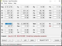
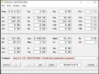
This is my first attempt to model an 8-inch subwoofer in Hornresp.
I have made two models and attached them here.
Kindly check the results.
(a) First two images ---> offset driver with straight TL
(b) Second two images ----> offset driver with 5:1 tapered TL
The driver datasheet is also attached.
1. How to ensure that the excursions are within Xmax?
2. What is the safe air velocity at the terminus of the TL?
3. What are the final check points to be enured before committing the design on wood?
Also, please suggest if there are any better alignments possible for this driver.
Thanks and regards,
Sumesh
Attachments


Hi,
is it possbile with Hornresp to simulate a hybrid bandpass-transmissionline?
Somehow like this:
Maybe with the ripole-model, with very long segments?
is it possbile with Hornresp to simulate a hybrid bandpass-transmissionline?
Somehow like this:
      / |
     /  |_______
    /S12|S21    /
   /    |\     /
  /     | ]   /
 /   S11|/   /
/_______|S22/
        |  /
        | /
Maybe with the ripole-model, with very long segments?
So i guess I will have to bite the bullet and invest a relevant amount of money in a miniDSP flex8 (or similar) and 2-3 extra tube amps 🙁
In any case, having the DSP to do the intial tuning before making a passive crossover can be useful. It's so much easier to experiment with crossover frequencies and slopes that way. You can also experiment with the audibility of time aligning and so on.
You may want to get some cheaper amps first. I'm sure older integrated amps can be had for very little at garage sales etc, and having a few extra amps for experiments is always handy. They will sound different from tube amps, but the tonality from the crossover/EQ will be fairly similar. Especially if you add a series resistor at the output to simulate the tube amp output impedance.
Do you believe this would be an effort worth of being pursued or should the power amp impedance matching just be disregarded when one wants to retain a certain flexibility with regards to the power amp to be paired to a horn ?
You can check this in Hornresp. You could design a few similar horns matched to various amp output impedances, and see how sensitive they are to changes in Rg. Impedance matching is most important for horns with small Cir.
Solid state amps I got PLENTY. Looks like I'm doomed to start hoarding tubes now LOL
With regards to Group Delay...I wonder if due to actual threshold of audibility of delay below 300Hz (it is not even measured in more recent studies) it is worth to delay the woofer or not.
With regards to Group Delay...I wonder if due to actual threshold of audibility of delay below 300Hz (it is not even measured in more recent studies) it is worth to delay the woofer or not.
- Home
- Loudspeakers
- Subwoofers
- Hornresp