Hello David,
Is there any plan to add a new type of flare for hornresp? like two parallels walls and curves surface?
Considering fixed S1 and S2 (2*S1), there would be infinite curved surfaces with different radius, don't know how hornresp could define the radius once changing the amount of input boxes will never happen. Maybe a semi-exponencial? two parallel walls and two exponencial walls, could it be reasonable?
As you can see in the attachment, for the Altec816 I emulated the curved surface with three parabolic segments, but there are some cases that having a curved flare would be good mainly saving segments.
Regards,
Marcelo
Attachments
Is there any plan to add a new type of flare for hornresp? like two parallels walls and curves surface?
Hi Marcelo,
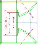
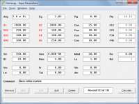
After reading your post I experimented with a test example to see what shape the equivalent axisymmetric horn segment would take, given the following inputs:
Throat width = 30 cm
Throat height = 11.28 cm
Mouth width = 30 cm
Mouth height = 252.31 cm
Axial length = 120 cm
Radius of curvature = 125 cm
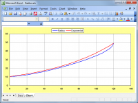
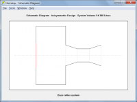
The blue trace in the attachment shows the axisymmetric profile of the "constant radius" segment specified above. The red trace shows the axisymmetric profile of an exponential segment having the same throat area, mouth area and axial length as the test segment.
While the profiles are certainly different, for simulation purposes the exponential flare is probably a reasonable approximation given that the segment is assumed to be axisymmetric anyway.
Finite element analysis techniques would need to be used to accurately model the blue profile, which unlike parabolic, conical and exponential flares, cannot be described by a relatively simple equation.
Based on past experience FEA would slow calculation times considerably, making it impractical to use multiple segments and "real-time" tools like the Loudspeaker Wizard.
Kind regards,
David
Attachments
Last edited:

Hornresp Update 5440-221023
Hi Everyone,
CHANGE
The PH4 Schematic Diagram on the main form and the Schematic and Schematic 1 diagrams in the PH4 Loudspeaker Wizard were not showing Segment 7 correctly. This has now been fixed.
Attachments 1 and 2 show the old incorrect diagrams. Attachments 3 and 4 show the new corrected diagrams (with absorbent filling material in segment 7).
Kind regards,
David
Attachments
It is likely that I set it to English when I first installed the OS, because I think the translations are still horrible after all these years, but Hornresp was working fine with the numpad up to the point of an update earlier this week.
Finite element analysis techniques would need to be used to accurately model the blue profile, which unlike parabolic, conical and exponential flares, cannot be described by a relatively simple equation.
Hello David,
Thanks for the analysis and the feedback.
I hope some colleague might arrive with a simplified equation that make it easy as parabolic, conical and exponential flares.
Numerical approach, like creating a polynomial to fit the axisymmetric exponential flare, would still slow down calculation times? Considering that CAD software draw some complex 3D shapes in real time, It might be some technique that may help.
Ragards,
Marcelo
I hope some colleague might arrive with a simplified equation
Just to clarify…
I really should have more completely said: "to accurately model the throat acoustical impedance of the blue profile horn segment", rather than simply: "to accurately model the blue profile".
Generating the blue profile curve itself is not that difficult, as shown in my earlier Excel chart screenprint 🙂.
Yes, the profile we see is the simplest part, also in background CAD do a lot of differential equations and so on. I can imagine the hard work behind each segment to define all its acoustical proprieties.
Considering the computers are very fast currently, would it be possible, maybe set up any preferences in hornresp so the user could accept to run some FEA in order to have more flare options? in case you are comfortable to work with this kind of solver. You could also cap how many segments could use asymmetrical flare. Maybe starting with just 1 I see how it works.

Considering the computers are very fast currently, would it be possible, maybe set up any preferences in hornresp so the user could accept to run some FEA in order to have more flare options? in case you are comfortable to work with this kind of solver. You could also cap how many segments could use asymmetrical flare. Maybe starting with just 1 I see how it works.
would it be possible, maybe set up any preferences in hornresp so the user could accept to run some FEA in order to have more flare options?
Too much work. It's not going to happen.
Hornresp currently has ten flare options (eleven if cylindrical is included). That's all you are going to get 🙂.
Attachments
Thank you David. We always need to try.
The last questions, from my curiosity once I'm not an audiophile, from all this profile the only one that consider two parallel walls is the parabolic, so all the others expands the 4 walls or are kind of circular, is this right?
The last questions, from my curiosity once I'm not an audiophile, from all this profile the only one that consider two parallel walls is the parabolic, so all the others expands the 4 walls or are kind of circular, is this right?
We are so limited as it is 10. Terrible. 😉Too much work. It's not going to happen.
Hornresp currently has ten flare options (eleven if cylindrical is included). That's all you are going to get 🙂.
from all this profile the only one that consider two parallel walls is the parabolic, so all the others expands the 4 walls or are kind of circular, is this right?
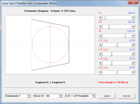
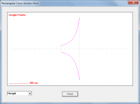
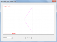
Any rectangular cross-section horn can have two parallel sides, it's just that with a parabolic flare horn the other two non-parallel sides will be straight panels because the overall area expansion rate of a parabolic horn is linear. For all other horn types, if two sides are parallel then the other two non-parallel sides will be curved rather than straight, to maintain the required area expansion rate of the horn in question.
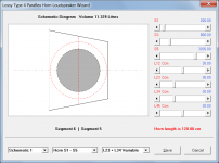
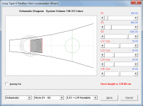
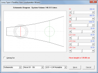
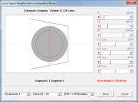
In the rectangular cross-section test examples shown attached, S1 = 1000 cm2, S2 = 10000 cm2, L12 = 100 cm and width (distance between parallel sides) = 30 cm.
Attachment 1 shows the height profile of a parabolic flare horn (note the straight sides).
Attachment 2 shows the height profile of a conical flare horn.
Attachment 3 shows the height profile of an exponential flare horn.
Attachment 4 shows the height profile of a Bessel horn with m = -2 (Gabriel's horn).
Attachments


Hello David,
That is very tricky, thanks for the effort to answer my questions. This means that the polynomial to fit needs to be created from my side (user) using CAD software, there is no need for you to change hornresp adding new profile.
While high tier CAD software has the ability to draw a line following any equations, FreeCAD only have basic geometries like: Arc, ellipse, hyperbola and parabola, so I might need to investigate for a rectangular cross-section horn with two parallel sides what is the closest flare available for each of those curves or just find the best so the automation will work well for curved flare too. I don't know if you saw but the list of available models now reach a very good place. https://freeloudspeakerplan.rf.gd/
I have other question that I'm going to post next
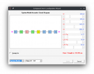
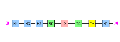
Regarding the Compound Horn as represented in the attachment #1 with the system model.
There is a loudspeaker design that I'm thinking to model in opposite direction (see attachment #1 you can think about the super scooper too), so it means that the Throat Chamber will work as Rear Chamber, but it rise a concern because the way you define both inputs are different, besides they can have the same volume (Vrc = Vtc) the second variable are different, for the rear chamber you define the length Lrc while for the throat you define the area Atc, from past simulations I saw that Lrc brings an important influence in the frequency response so I may loose accuracy if I use one to emulate the other. In case it's not recommended to follow this path. Would it be possible to create a new Compound Horn (CH2) in order to allow just one segment (H1) in the front side connected to the throat chamber/port and move the others 2 segments (H2 and H3) to the rear chamber connected to the H4 segment? see the attachment #2 and 3 Or even 4 segments in the rear chamber in this case it could be a new type of single driver like Nb1.
In a Compound Horn (CH) I was not able to double click in the throat adapter (Ap1 + Lp) and replace it with Acoustical Lining (Far + Tal) is this a bug from Linux or in fact this option isn't available for CH?
Attachments

https://wiki.freecadweb.org/Curves_WorkbenchHello David,
That is very tricky, thanks for the effort to answer my questions. This means that the polynomial to fit needs to be created from my side (user) using CAD software, there is no need for you to change hornresp adding new profile.
While high tier CAD software has the ability to draw a line following any equations, FreeCAD only have basic geometries like: Arc, ellipse, hyperbola and parabola, so I might need to investigate for a rectangular cross-section horn with two parallel sides what is the closest flare available for each of those curves or just find the best so the automation will work well for curved flare too. I don't know if you saw but the list of available models now reach a very good place. https://freeloudspeakerplan.rf.gd/
I have other question that I'm going to post next
I have also scanned to BMP or printed and scanned curves that I needed to make for complex waveguides. It can be done in FreeCAD. I am no expert. But I am determined 😉
I don't know if you saw
Yes, I have.
It's amazing work, well done.
it means that the Throat Chamber will work as Rear Chamber, but it rise a concern because the way you define both inputs are different, besides they can have the same volume (Vrc = Vtc) the second variable are different, for the rear chamber you define the length Lrc while for the throat you define the area Atc
Atc rather than Ltc is used as one of the two throat chamber parameters just to make things a little easier, because often Atc is specified simply as being equal to Sd, or n x Sd for multiple drivers.
Ltc is still used in the simulation model itself though, and is calculated as Vtc / Atc.
In a Compound Horn (CH) I was not able to double click in the throat adapter (Ap1 + Lp) and replace it with Acoustical Lining (Far + Tal)
The Fr + Tal acoustical lining model is only suitable for use with closed rear chambers. The throat chamber resonances can however be hidden using the "resonances masked" option.
Notes:
1. The maximum value of Vtc can be 999999.9 or almost 1000 litres.
2. No internal end correction is included when the port tube is specified using horn segments.
3. The design could alternatively be configured as shown in the attachments, with the "resonances not masked" option results being identical. If required, absorbent filling material could also be added to the segment 1 "chamber".
Attachments
The Hornresp Input Wizard expressed in flowchart form:
https://www.diyaudio.com/community/threads/hornresp-flowchart.391554/#post-7156312
https://www.diyaudio.com/community/threads/hornresp-flowchart.391554/#post-7156312
- Home
- Loudspeakers
- Subwoofers
- Hornresp