You are Such an excellent guy. the world could use a bit more McBean in it!💚. thank you so much

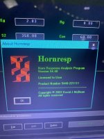
Hornresp Update 5440-221111
Hi Everyone,
CHANGE
Results can no longer be calculated with the Ctrl key depressed (Booger weldz to particularly note).
BUG FIX 1
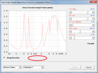
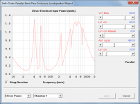
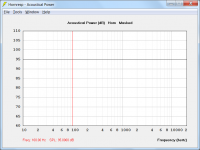
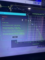
The "Frequency (hertz)" x-axis label was missing from the Driver Electrical Input Power chart in the Band Pass Enclosure Loudspeaker Wizard, as shown in Attachment 1. This has now been fixed, as shown in Attachment 2.
BUG FIX 2
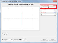
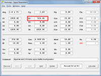
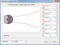
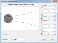
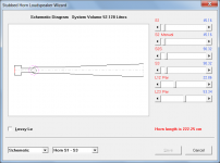
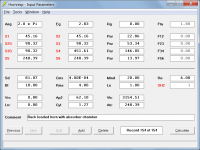
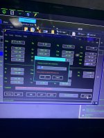
When the Loudspeaker Wizard area slider control for an H-frame or a U-frame system was adjusted and the results saved back to the main input parameters window, the S2 value was not being updated as shown in Attachments 3 and 4. This has now been fixed.
BUG FIX 3
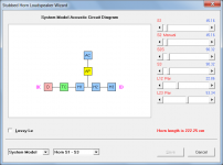
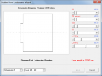
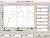
In the Loudspeaker Wizard Schematic Diagram for a stubbed horn, acoustical lining material in the rear chamber had display precedence over absorbent filling material in the stub, as shown in Attachment 5. This display precedence has now been reversed, as shown in Attachment 6.
Kind regards,
David
Hi Everyone,
CHANGE
Results can no longer be calculated with the Ctrl key depressed (Booger weldz to particularly note).
BUG FIX 1
The "Frequency (hertz)" x-axis label was missing from the Driver Electrical Input Power chart in the Band Pass Enclosure Loudspeaker Wizard, as shown in Attachment 1. This has now been fixed, as shown in Attachment 2.
BUG FIX 2
When the Loudspeaker Wizard area slider control for an H-frame or a U-frame system was adjusted and the results saved back to the main input parameters window, the S2 value was not being updated as shown in Attachments 3 and 4. This has now been fixed.
BUG FIX 3
In the Loudspeaker Wizard Schematic Diagram for a stubbed horn, acoustical lining material in the rear chamber had display precedence over absorbent filling material in the stub, as shown in Attachment 5. This display precedence has now been reversed, as shown in Attachment 6.
Kind regards,
David
Attachments
Is there a possibility in a Force flat response feature to view all the common details by???
For example, when viewing driver excursion...If we could force a neutral FR, the excursion would show itself, in a useful way. When in "neutral mode" FR is always a 0 transfer function allowing one another view of excursion and surrounding details like port velocity, etc.... many people are designing towards a 0 transfer function, so this feature helps to judge efficiency/headroomIt is not clear to me what you mean. Can you please provide further information.
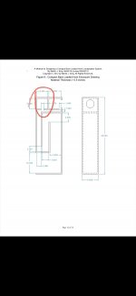
Apologies, My question is premature. I see there have been posts referring to use of stubs I should study first.
The attachments below should hopefully help you to fast-track the study requirements 🙂.I see there have been posts referring to use of stubs I should study first.
Attachments
Last edited:
If we could force a neutral FR
By "neutral FR" do you mean a constant power response across the frequency range, as shown in the attachment?
Attachments
Has anyone loaded up the new version of horn response and looked into the -Easter egg—?? I gotta get a new laptop here quickly so I can check it out. My junk is broken.
Thankyou David, sure did cut down the learning curve. It looks like the absorber chamber does smooth the midrange nicely but the bass still has a dip I wasn't able to fill. When I compare to the standard offset horn, overall I think it looks better. An offset backloaded horn with an absorber chamber might be a good option if that were possible.The attachments below should hopefully help you to fast-track the study requirements 🙂.
Attachments
An offset backloaded horn with an absorber chamber might be a good option if that were possible.
It's not going to happen - would require too much work at this stage.
Has anyone loaded up the new version of horn response and looked into the -Easter egg—??
I certainly have 🙂.
Attachments
wow!! The perfect 3:1 split between resonators…. ….(geek moment) 86400 seconds in a day and so much moreHa!!! 💚👍🏼💚
Attachments
Last edited:
I see from your attachments above that you had no problem finding the Easter Egg 🙂.Ha!!! 💚👍🏼💚
Truely fantastic🌚🌒🌓🌔🌕🌖🌗🌘🌚I see from your attachments above that you had no problem finding the Easter Egg 🙂.
The attachments below should hopefully help you to fast-track the study requirements 🙂.
Is there any explanation for the dip and peak below 100hz in the stubbed horn model output? I can achieve a rolled of smooth response by increasing the coupling volume (increases length) but that would be impractical--I think. I tried masking/unmasking throat resonances as well. Thanks for any feedback. Datafile attached.Thankyou David, sure did cut down the learning curve. It looks like the absorber chamber does smooth the midrange nicely but the bass still has a dip I wasn't able to fill. When I compare to the standard offset horn, overall I think it looks better. An offset backloaded horn with an absorber chamber might be a good option if that were possible.
Attachments
Hornresp Update 5440-221119
Hi Everyone,
CHANGE
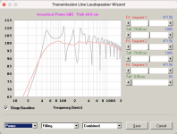
Previously the three TL Design tool methods were accessed in the following order:
BS 2022
MK 2006
MK 2021 (Alignments A, B and C)
1. This order has now been changed so that the method striking the best overall balance between cabinet size and performance is placed first.
2. MK 2006 and MK 2021 have been renamed as MJK 2006 and MJK 2021 respectively.
3. Method MJK 2021 in effect supersedes MJK 2006.
The new order is:
MJK 2021 (Alignments A, B and C)
MJK 2006
BS 2022
BUG FIX
The results produced by the TL Design tool were in some cases slightly inaccurate. This problem has now been fixed and all results are now correct.
Kind regards,
David
Hi Everyone,
CHANGE
Previously the three TL Design tool methods were accessed in the following order:
BS 2022
MK 2006
MK 2021 (Alignments A, B and C)
1. This order has now been changed so that the method striking the best overall balance between cabinet size and performance is placed first.
2. MK 2006 and MK 2021 have been renamed as MJK 2006 and MJK 2021 respectively.
3. Method MJK 2021 in effect supersedes MJK 2006.
The new order is:
MJK 2021 (Alignments A, B and C)
MJK 2006
BS 2022
BUG FIX
The results produced by the TL Design tool were in some cases slightly inaccurate. This problem has now been fixed and all results are now correct.
Kind regards,
David
Is there any explanation for the dip and peak below 100hz in the stubbed horn model output?
The main reason is because the horn mouth is so small, causing significant reflections due to the acoustical impedance mismatch at the mouth.
You may possibly be better served by using a tapered transmission line design instead.
- Home
- Loudspeakers
- Subwoofers
- Hornresp