when designing in BR, do I need to set a Path length?
Ideally yes. Hornresp treats the outputs as two point sources, with the enclosure considered to be effectively "invisible". The Path length is the distance separating the two point sources.
In practice, depending upon the system dimensions, sometimes specifying the path length makes little difference to the results. The easiest way to check this is to adjust the Path slider in the Loudspeaker Wizard and see what effect it has on the combined response.

Hi David, hi all 🙂
i was playing arround with some compound horn with rear chamber, when i seemed to find an error.
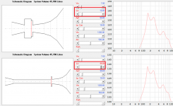
While simulating the rear chamber, there is absolutely NO effect at all, varrying the chamber depht (Lrc) as you can see.
I am pretty sure this has some heavy impact in reality. Am i doing something wrong here?
On the other side, while modeling the same volume of air with the same shape, i get different results... depending if i use the horn (S5+S6+L56) or the chamber (Vrc+Lrc) to model it... while keeping the other stat at 0,1.
Any ideas?
i was playing arround with some compound horn with rear chamber, when i seemed to find an error.
While simulating the rear chamber, there is absolutely NO effect at all, varrying the chamber depht (Lrc) as you can see.
I am pretty sure this has some heavy impact in reality. Am i doing something wrong here?
On the other side, while modeling the same volume of air with the same shape, i get different results... depending if i use the horn (S5+S6+L56) or the chamber (Vrc+Lrc) to model it... while keeping the other stat at 0,1.
Any ideas?
Attachments
i was playing arround with some compound horn with rear chamber, when i seemed to find an error.
Hi TechnicSummse,
Thanks for the feedback. The good news is that the results you are getting are not due to a bug 🙂.
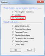
To obtain the results you were hoping to see for both the test examples you provided, simply change the chamber resonances option from "Masked" to "Not masked".
When the "Masked" option is selected the air volumes in the front and rear chambers are treated as a simple acoustic compliances. For the rear chamber this means that only Vrc is taken into account, and changing Lrc makes no difference to the results.
Rear chamber acoustical reactance Xar = -1 / (w * Car)
Where:
w = 2 * Pi * f
Car = Vrc / (rho * c ^ 2)
And:
f = frequency
rho = air density
c = speed of sound
(Most loudspeaker box simulators in effect use the "Masked" option, which is why only volume needs to be specified when using those programs).
Kind regards,
David
Attachments
Hi TechnicSummse,
Thanks for the feedback. The good news is that the results you are getting are not due to a bug 🙂.
To obtain the results you were hoping to see for both the test examples you provided, simply change the chamber resonances option from "Masked" to "Not masked".
When the "Masked" option is selected the air volumes in the front and rear chambers are treated as a simple acoustic compliances. For the rear chamber this means that only Vrc is taken into account, and changing Lrc makes no difference to the results.
Rear chamber acoustical reactance Xar = -1 / (w * Car)
Where:
w = 2 * Pi * f
Car = Vrc / (rho * c ^ 2)
And:
f = frequency
rho = air density
c = speed of sound
(Most loudspeaker box simulators in effect use the "Masked" option, which is why only volume needs to be specified when using those programs).
Kind regards,
David
Hey David, thanks for the fast help.
I think i get the point here... but adding a port/horn to the chamber adds a second output wich varries with chamber lenght, right?
Whats the benefit, of ignoring the Lrc, besides simpler calculating?
but adding a port/horn to the chamber adds a second output wich varries with chamber lenght, right?
Correct.
Changing the chamber length alters the position of the resonances.
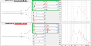
The attachment compares the masked (grey trace) and unmasked (black trace) response results for a standard ("Normal") bass reflex loudspeaker radiating into half space, created using the Input Wizard.
The chamber resonances in the unmasked response at higher frequencies can be clearly seen. The rear chamber depth Lrc is 20 cm and the speed of sound is assumed to be 34400 cm/sec.
Lrc = 0.5 wavelengths at 860 Hz
Lrc = 1.0 wavelength at 1720 Hz
Lrc = 1.5 wavelengths at 2580 Hz
Lrc = 2.0 wavelengths at 3440 Hz
Lrc = 2.5 wavelengths at 4300 Hz
And so on…
If Lrc is changed, the resonance positions alter accordingly.
Whats the benefit, of ignoring the Lrc, besides simpler calculating?
The Masked option enables Hornresp results to be directly compared against those produced by other simulation programs that use the simplified air chamber compliance model. Also, using the Masked option is another way of showing how adding acoustical lining material to an enclosure can dampen resonances.
Attachments
Is 4 segments limit hard coded or can't I just find a command to add more segments?
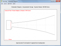
Hornresp is limited to 4 segments except in the special case of Paraflex horns, where 7 segments are used.
In some designs a throat adaptor can be specified to in effect add a fifth segment, as shown in the attachment.
Attachments
Well the evil empire of diyaudio has not sent me updates once again for two weeks. I am posting to hopefully feed the algorithm that decides when and where I will be getting updates.
A lot of tweaks on the program David. Things that I have not even looked at! How do I keep up!!
A lot of tweaks on the program David. Things that I have not even looked at! How do I keep up!!
I missed the last update somehow but other than that when I click on the thread watch button at the beginning of the thread, the latest feed is pretty reliable.Well the evil empire of diyaudio has not sent me updates once again for two weeks. I am posting to hopefully feed the algorithm that decides when and where I will be getting updates.
A lot of tweaks on the program David. Things that I have not even looked at! How do I keep up!!
I know this might be the wrong place for this question, but since Hornresp-results bring me to this question, ill just ask it here 😀
Is there a rule of thumb for maximum compression ratio with strong motor high excursion drivers?
I'm getting the best simulation results with compression ratios of roughly 10:1 (cone area vs throat area).
I was reading about an upper limit of like 3:1, because of cone weakness in general. But in my understanding, this should be higher for stronger cones. Also it should depend on the size of the frontchamber?
If there is a bigger frontchamber, there is less overall pressure on the cone, no matter what size the throat of the attached horn has.
Just to clarify, i am talking about 2x 8" subs, front chamber 2-3l and Ap1 of 40-50cm²
What do you think?
Is there a rule of thumb for maximum compression ratio with strong motor high excursion drivers?
I'm getting the best simulation results with compression ratios of roughly 10:1 (cone area vs throat area).
Think as the driver's cone as a piston, and the throat as a restriction for the air to flow, more restriction you have harder will be for the air to flow, this "difficult" will translate into pressure over the cone (pressure = force / area). Each driver use different cone material, and each material have different strengths to resist force (Material Ultimate Strength Property). There are some driver that has reinforced cones, so they are able to resist higher forces.
You can use as much compression ratio as you want, as long as you adjust the input power according to the cone material Ultimate Strength Property and related duty cycle for proper life. Too complicate for non engineers.
Let's think you don't know how much pressure the cone can resist and its made from "paper".
1) For a safer result, you could simulate a vented box, set the voltage to achieve Xmax
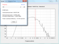
2) open the diaphragm displacement chart
3) Go to tools diaphragm pressure ( check all pressure and take note of the maximum value.
Back to your original design with 10:1 compression ratio
Set Eg for 1W, and start to increase it until you reach the same diaphragm pressure value as vented box, probably you will be very limited in terms of output power, and the diaphragm displacement will be lower then Xmax because you are now working with higher pressure condition. so you probably will need to define the best trade of for you. Maybe for home use you can accept to live with lower output in order to use higher compression ratio.
You can also use higher compression ratio and the maximum output power at the same time, but you may reduce the drive cone life drastically and you may start o face distortions in the sound because the cone hasn't enough strength for that pressure level and stranger deformations /wobbling will occur.
I was starting to wonder where you had gone 🙂.I am posting to hopefully feed the algorithm that decides when and where I will be getting updates.
I don't post that often. I doubt I am missed that much 🙂I was starting to wonder where you had gone 🙂.
Amazing information!Think as the driver's cone as a piston, and the throat as a restriction for the air to flow, more restriction you have harder will be for the air to flow, this "difficult" will translate into pressure over the cone (pressure = force / area). Each driver use different cone material, and each material have different strengths to resist force (Material Ultimate Strength Property). There are some driver that has reinforced cones, so they are able to resist higher forces.
You can use as much compression ratio as you want, as long as you adjust the input power according to the cone material Ultimate Strength Property and related duty cycle for proper life. Too complicate for non engineers.
Let's think you don't know how much pressure the cone can resist and its made from "paper".
1) For a safer result, you could simulate a vented box, set the voltage to achieve Xmax
2) open the diaphragm displacement chart
3) Go to tools diaphragm pressure ( check all pressure and take note of the maximum value.
Back to your original design with 10:1 compression ratio
Set Eg for 1W, and start to increase it until you reach the same diaphragm pressure value as vented box, probably you will be very limited in terms of output power, and the diaphragm displacement will be lower then Xmax because you are now working with higher pressure condition. so you probably will need to define the best trade of for you. Maybe for home use you can accept to live with lower output in order to use higher compression ratio.
You can also use higher compression ratio and the maximum output power at the same time, but you may reduce the drive cone life drastically and you may start o face distortions in the sound because the cone hasn't enough strength for that pressure level and stranger deformations /wobbling will occur.
Thank you so much.
When checking for diaphragm pressure with different variables... i realised that the "filling" set up in the loudspeaker wizzard is not taken over to the calculation.
Is there a way to see diaphragm pressure with added filling? I have a pretty big spike at the lowest resonant frequency, wich i even out with filling.
When calculating the manufacturer proposal ported box, i end up with a max of 8Kpa, while ending with 20Kpa spike with 10:1 ratio. I guess this is not perfect 😀
@ David McBeanThink as the driver's cone as a piston, and the throat as a restriction for the air to flow, more restriction you have harder will be for the air to flow, this "difficult" will translate into pressure over the cone (pressure = force / area). Each driver use different cone material, and each material have different strengths to resist force (Material Ultimate Strength Property). There are some driver that has reinforced cones, so they are able to resist higher forces.
You can use as much compression ratio as you want, as long as you adjust the input power according to the cone material Ultimate Strength Property and related duty cycle for proper life. Too complicate for non engineers.
Let's think you don't know how much pressure the cone can resist and its made from "paper".
1) For a safer result, you could simulate a vented box, set the voltage to achieve Xmax
2) open the diaphragm displacement chart
3) Go to tools diaphragm pressure ( check all pressure and take note of the maximum value.
Back to your original design with 10:1 compression ratio
Set Eg for 1W, and start to increase it until you reach the same diaphragm pressure value as vented box, probably you will be very limited in terms of output power, and the diaphragm displacement will be lower then Xmax because you are now working with higher pressure condition. so you probably will need to define the best trade of for you. Maybe for home use you can accept to live with lower output in order to use higher compression ratio.
You can also use higher compression ratio and the maximum output power at the same time, but you may reduce the drive cone life drastically and you may start o face distortions in the sound because the cone hasn't enough strength for that pressure level and stranger deformations /wobbling will occur.
Remember when I asked for this option? Diaphragm pressure. Particle velocity too! You thought it would never get used! These guys are smart. Same goes for the Wizard. What would we do without the Loudspeaker wizard! And you didn't want to do it. Well to be fair you pointed out how slow the calculations were. And I argued all we do is make horn flare approximations anyway. And now look at what you have done! Enclosures that pretty much only Hornresp can simulate. And pretty much the only simulator that will simulate internal enclosure resonances. I still talk with engineers that have never heard of Hornresp. And doubt it. It's free! How good could it be?
Free is not necessarily bad. And a more verified program for loudspeaker design I do not think exists.
Happy Sunday to all.
Play some tunes!
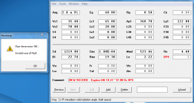
OK, what 'null' did I manage to miss this time? 


edit: Note the original and new copy was saved in the Records file and have been able to update/save both.
edit: Note the original and new copy was saved in the Records file and have been able to update/save both.
Attachments
Last edited:
Is there a way to see diaphragm pressure with added filling?
No, it can only be done with acoustic lining material added.
I definitely remember Mårten (more10) asking for it in Post #3,206. It prompted the release of Version 31.30 🙂.Remember when I asked for this option? Diaphragm pressure. Particle velocity too!
https://www.diyaudio.com/community/threads/hornresp.119854/page-161#post-3420434
Last edited:
OK, what 'null' did I manage to miss this time?
This is really weird, I have no idea what is causing the Error 94 problem you are intermittently experiencing. I have tried everything I can think of but have not been able to replicate the problem.
Not one else has reported a similar issue and I am at a loss to explain why it should be you only - you're just lucky, I guess 🙂.
I think we both did. I also looked around that time on this thread and found that I asked for the crossover additions too. Don't know if that was the first request. But Jean Michel Le Cleach chimmed in too. I miss him. He was a great guy.I definitely remember Mårten (more10) asking for it in Post #3,206. It prompted the release of Version 31.30 🙂.
https://www.diyaudio.com/community/threads/hornresp.119854/page-161#post-3420434
Mark
- Home
- Loudspeakers
- Subwoofers
- Hornresp