What's the possibility of having it look like the second, for the "closed horn" model?
Not sure. I will have a look, but it may be difficult to justify the amount of work required to implement the change. While it might appear to be just a minor modification, as far as Hornresp is concerned, it's not - it's a major one 🙂.
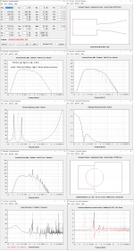
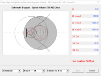
Hi Brian - that box is roughly the size of Bill Woods' "Hitbox" so I did a comparison - not real far off in response, excursion - but the input impedances are vastly different? Maybe I screwed something up in copying your input screen (?) What makes the difference ? I assume its from the large "throat". Maybe Oliver Read's and Daniel Cohen's BVR have similar input Z characteristics.
Attachments
Last edited:
Hi everyone
Why passive radiators have negative group delay levels?
That's a feature of PR alignments. It's due to the phase change around the passive radiator's resonance frequency. You should see a notch in the overall FR around that same frequency.
Hi Brian - that box is roughly the size of Bill Woods' "Hitbox" so I did a comparison - not real far off in response, excursion - but the input impedances are vastly different? Maybe I screwed something up in copying your input screen (?) What makes the difference ? I assume its from the large "throat". Maybe Oliver Read's and Daniel Cohen's BVR have similar input Z characteristics.
The electrical impedance (grey) definitely looks off. Is that for the hitbox or for my offset-vent box? If the latter, then something was entered incorrectly, as that impedance curve looks like what I'd expect from a sealed box.
hi Brian - the gray was your box - - I goofed it for sure but not sure "where" (other than "exp" which should not matter nuch)
Attachments
Last edited:
The driver is at S2 and the vent is at S3. L23 covers the section between the driver and the vent.
Looks like a bug in Hornresp. It's triggered when you select the "Lossy Le" option. Deselect it and you'll get the correct impedance curve.
You should be using the semi-inductance option instead anyway 🙂
You should be using the semi-inductance option instead anyway 🙂
The driver is at S2 and the vent is at S3. L23 covers the section between the driver and the vent.
Got it!
Looks like a bug in Hornresp.
It is indeed - it will be fixed in the next update.
What's the possibility of having it look like the second, for the "closed horn" model?
If all goes according to plan, it will be in the next update.
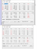
I think I had a bug in using the Input Wizard to set up a driver and passive radiator enclosure. I had very strange output. And it made no sense at all. So I compared the same design to Unibox. Another well documented program for simulation. And the results were more inline with what I was thinking. With the latest version everything worked perfectly.
I also think that I had a real Bozo moment when I clued in that an offset driver is a normal driver configuration on a baffle for a normal enclosure. I hope! Sometimes the things that escape me are crazy.
I also think that I had a real Bozo moment when I clued in that an offset driver is a normal driver configuration on a baffle for a normal enclosure. I hope! Sometimes the things that escape me are crazy.
Updated hornresp to version 52.10
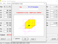
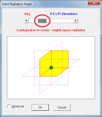
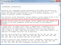
I have no sliders or no ability to change those functions. Is this a bug in the update? Tried saving my dat files, driver files, and import files in a different folder. Deleted old hornresp folder and reinstalled. still the same.
photo is radiation angle. I have no way of adjusting it along with anything else that had a slider.
Attachments
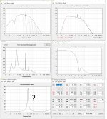
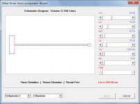
I am trying to model a behavior of two Beyma 8G40 in a synergy type speaker.
What i am trying to see is how the chamber between diaphragm and horn wall (along with port size and length) affect upper end response of the driver. And how the position of the injection port affect the notch in the upper end.
The horn i use is XT1464. And here is how i model it:


Basically, it is a bandpass of 4th order being 'injected' into a horn of specific parameters. Closed chamber in this case is the rear volume and throat chamber is what between the diaphragm and the horn wall.
Am i missing something here or is it this straightforward?
And one more question - i have two drivers attached on the horn. When i describe the model in HornResp, should i double the values for Vrc, Ap1, Vtc? Or should i describe parameters per driver and then just choose 2 drivers in the menu?
What i am trying to see is how the chamber between diaphragm and horn wall (along with port size and length) affect upper end response of the driver. And how the position of the injection port affect the notch in the upper end.
The horn i use is XT1464. And here is how i model it:
Basically, it is a bandpass of 4th order being 'injected' into a horn of specific parameters. Closed chamber in this case is the rear volume and throat chamber is what between the diaphragm and the horn wall.
Am i missing something here or is it this straightforward?
And one more question - i have two drivers attached on the horn. When i describe the model in HornResp, should i double the values for Vrc, Ap1, Vtc? Or should i describe parameters per driver and then just choose 2 drivers in the menu?
Updated hornresp to version 52.10
I have no sliders or no ability to change those functions.
Same issue here.
Attachments
Same issue here.
Luckily i have an older version on my other laptop so i can still use for now. Im sure once David see's this it will get addressed.
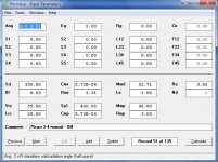
Could you please post the input parameter values for the loudspeaker system design that produces the result you show.
Attachments
Im sure once David see's this it will get addressed.
Unfortunately I cannot help you with this one - everything continues to work just fine for me on Windows 7. The coding changes made in the latest release could not have possibly caused the problem you are seeing. What operating system are you using, and has it perhaps been updated recently, introducing an incompatibility issue?
Attachments
Am i missing something here or is it this straightforward?
It is that straightforward if you don't want to include the effect of the high frequency driver at the horn throat. If you do, then simulate as a two-way multiple entry horn system instead.
The throat chamber length in your example is not very realistic... 🙂.
should i double the values for Vrc, Ap1, Vtc?
The values specified for Vrc, Ap1, Vtc and Atc should be the total volumes and areas as seen by the two drivers.
Attachments
- Home
- Loudspeakers
- Subwoofers
- Hornresp