How to model BLH coupling chamber
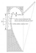
I'm new to loudspeaker design and to Hornresp. I have a reasonable handle on how to model the BLH design I'm developing, but I'm struggling with how to model elements of the coupling chamber. The design supports offsetting the driver location anywhere along the length of the chamber (See the image), but I'm confused about how to model that, as well as a few other terms. Given a driver offset in a throat/coupling chamber, does Vrc - Vtc = the offset? Is Lp simply the thickness of the plywood in the throat port in the attached image?
Basically, any advice in how to go about modeling this is most appreciated.
Thanks in advance!
Attachments
Last edited:
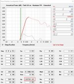
Maybe this is helpful...
View attachment 909193
And measurement 0cm from mouth:
View attachment 909198
Yes, this is perfect! Very nice😱
I believe Zd is used in a tapped horn. In a horn with a coupling chamber, the volume of the chamber, the driver and the are of the output are considered a slug.
And also, while making things look pretty, a smooth BLH is counterproductive.
dave
And also, while making things look pretty, a smooth BLH is counterproductive.
dave
Forgive my ignorance: What's Zd? Not seeing it in the hornresp help or the MJ King horn physics papers. And what do you mean by "slug"?
The smoothness wasn't for pretty, it was to maintain an exponentially expanding cross-section. Are you saying that's counter-productive? The woodworking for that is easy for me--that's my domain.
Thanks--appreciate the help.
The smoothness wasn't for pretty, it was to maintain an exponentially expanding cross-section. Are you saying that's counter-productive? The woodworking for that is easy for me--that's my domain.
Thanks--appreciate the help.
Okay, I see Z is impedance, but more to the point, as I continue to noodle on this, per the HR help doc, I think modeling this as an Offset Driver Horn instead of a BLH is looking like the best way to go, given the way I'm placing the driver.
is there a fraction or multiplier engaged to the parts of OD, thats then a back wave for TH also? A guideline or similar to grab a firm understanding of probably the most interesting and challenging horn layout and creation if i was trying to pick to date.
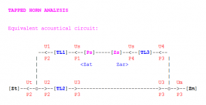
I am not aware of any guidelines or "rules of thumb" when it comes to analysing the performance of tapped horns. Determining the pressures P and volume velocities U through the equivalent acoustical circuit (see attachment) are not trivial processes because of the way that the outputs from both sides of the driver diaphragm are combined within the system. Hornresp does a complete analysis of the acoustical circuit, taking all these pressures and volume velocities into account. The interactions are extremely complex, with the effects on response not easy to intuitively predict. The simulation model needs to solve 12 simultaneous equations to obtain the required results.
Attachments
Maybe this is helpful...
It certainly is, thanks.
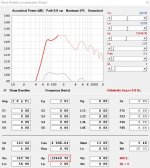
I am quite surprised that the predicted and measured results are as close as they are, considering the differences between the simulation model and the actual loudspeaker design.
I'm struggling with how to model elements of the coupling chamber. The design supports offsetting the driver location anywhere along the length of the chamber
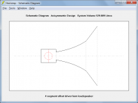
Does the attached design (not to scale) perhaps go some way towards meeting your requirements?
Attachments
Maybe this is helpful...
View attachment 909193
And measurement 0cm from mouth:
View attachment 909198
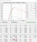
Interestingly enough that sim is a little bit off. The box is a 36" x 24" x 36" box, and the Hornresp sim gives a net box volume that's 9% larger than the actual net box volume once you calculate the gross volume and subtract the volume occupied by the panels.
The BOXPLAN workbook generates a sim with a net box volume that's a lot closer to the calculated net box volume. Even then, there are some curious things happening, as the measured Fb for that build seems to be quite a bit lower than predicted by the sim - it's almost like the box is slightly larger or deeper.
Attachments

This is partly due to internal end corrections in the BP6P simulation model increasing the effective lengths of the port tubes. Other differences in the results are due to the basic system models / topologies not being exactly the same.
Thanks for this David.
I was working from the premise that if the physical topology of the box as described in both models is close, then the results predicted by both models should also be close. It looks like in this case the TH model for the layout generates results that are pretty close to the measured results, but the BP6P model generates results that show a noticeable "null" in the usable passband that does not appear in the measured response of the built system.
I'm going to repeat this exercise this weekend with the BOXPLAN-BP62 that I used to describe a series-tuned 6th order BP fold. It should be possible to generate a Hornresp TH model for that instead that's an exact topological match to the one described by the existing BP6S model being generated by the workbook. If the two models end up predicting appreciably different results, I may just have to build the thing and measure it, to see which Hornresp model gave the more accurate prediction 🙂.
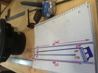
Brian, here is the design what has been build from the sim.
View attachment 909471
Yeah, the sim was definitely off then.
Look at the mouth - the dimensions are 550 mm x (243x2) mm That gives a CSA of 2673 cm^2 for S4, not 2750 cm^2. Seeing the size of the chamber of this CSA in the box, that should impact the sim a bit.
Also, if the mouth is 550 mm wide, there's no way the box itself is 24" wide unless they used double-thick side panels. 55+(1.9*2))= 58.8 cm = 23.1 ".
If I have a chance later I'd post up another updated sim, but you can see what it's going to be like if you download the BOXPLAN-PARAC workbook and input the external dimensions, panel thickness and correct value for S4 that was actually used for the build.
Everything seems to be working just fine for me. Are you following the sequence of events detailed in Post #11416? If not, what are you doing differently that is causing the problem?
FWIW, I just ran into this issue as well. I created two new Hornresp sims, and when I went to close Hornresp, it did not prompt me to save like it normally does.
I'm using the latest version.
Does the attached design (not to scale) perhaps go some way towards meeting your requirements?
Yes! That's it. Thank you, David. It'll actually be a little simpler, since the horn-part itself is a single exponential segment, although the aspect ratio of the rectangular cross section slowly changes closer to square on the "external" part of the horn behind the main cabinet.
Thanks again!
Bug in calculating resonance-2?
Hello David,
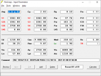
I was playing with a BR model, with impedance and resonance, I noticed that the resonance frequency was varying drastically within a narrow range of values. Is this a bug or implicit to the model and assumptions used.
Hello David,
I was playing with a BR model, with impedance and resonance, I noticed that the resonance frequency was varying drastically within a narrow range of values. Is this a bug or implicit to the model and assumptions used.
Attachments
What's Zd?
It is an MJK term. The distance between where the driver is mounted and the closed end of the box.
In this ML-TL 465 mm
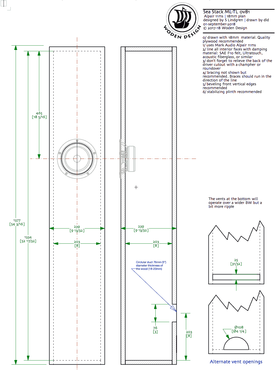
dave
The acoustic circuits are a bit different, but in terms of topology the models are pretty close, so I expected the sim results to be pretty close. However the BP sim puts a pretty big dip in the middle of the passband that does not show up in the TH sim.
FWIW, measurements show that the TH sim is the more accurate one, even though it doesn't take the impact of the offset driver in Vrc into consideration.
I've attached a diagram showing how the sims were created. Yes, I moved the vent a little - I didn't expect moving it from the edge of the mouth to just outside the mouth would make such a big difference in the middle of the passband. I guess it would be more accurate to model it as a series-tuned 6th order system, but Hornresp doesn't provide a means to model an offset rear vent.
Brian, can you clarify which one is BP and which is TH? And what are these shorthand for? Bandpass and ... or something else?
It is an MJK term. The distance between where the driver is mounted and the closed end of the box.
In this ML-TL 465 mm
dave
Yes, but the application of that Martin is revising. and it seems to agree with Hornresponse every step of the way. in the applications used in CH and also some versions of TH. (If you try and see) But Martin isnt looking at THs he is instead interrupting Zd from either end.(not interupting it i could say?) so far at exact phase intervals with the driver location at either. no longer at the 1/3,2/3 split, but the rest is his personal info and he might share that at somepoint? Meanwhile, hes not the only one playing with sim software. and because of David we all have a bit of a leap frog into areas we never could otherwise.
that leap frog is okay if you know where you landed. im not martin or david. I just like where they dropped me off. martins map is only in kansas. Its very thorough, but it is Kansas(wizard of OZ pun intended)..
david can take us to OZ.. i dont have that map, but i need to realize there is a compass somewhere? We all could use a compass if we wanted to create one?
It is an MJK term. The distance between where the driver is mounted and the closed end of the box.
In this ML-TL 465 mm
dave
I am not aware of any guidelines or "rules of thumb" when it comes to analysing the performance of tapped horns. Determining the pressures P and volume velocities U through the equivalent acoustical circuit (see attachment) are not trivial processes because of the way that the outputs from both sides of the driver diaphragm are combined within the system. Hornresp does a complete analysis of the acoustical circuit, taking all these pressures and volume velocities into account. The interactions are extremely complex, with the effects on response not easy to intuitively predict. The simulation model needs to solve 12 simultaneous equations to obtain the required results.
This is excellent!
if narrowing down 4 quadrants into 1/3 2/3 (reflected in offset, offset, then twice to exit) its misfing the folding?. All in lengths divided in qurter. i get the same in ‘assumption’ ?? 12 repeats itself it seems, and its unique or coincidental i dont yet realize but this might show what i mean in the way, this is a step backward by (half). But i think i need to revisit this to guess whats not here or in the folding response? in each which accumulstes?
Attachments
Last edited:
Yes, but the application of that Martin is revising. and it seems to agree with Hornresponse every step of the way.
Yes, MJK’s models and HornResp can get you to the same place, and sadly MArtin’s is NLA.
I find the graphs people post of Hornresp sims are hard to read. David has shown that daming can be added to better show the end result, but few seem to take advanatge of that.
Caveat: They both only run on Windoz so i do not use either. Scott does all the horns and TLs.
dave
- Home
- Loudspeakers
- Subwoofers
- Hornresp