Thanks Brian.Check the BOXPLAN-ODOV and BOXPLAN-VBSLOT workbooks available at the link: http://www.diysubwoofers.org/sheets/
The first one is an approximation (the Hornresp model is not quite exact, as the vent is inside, not outside, the enclosure).
The second one matches the Hornresp model exactly.
Mark
Ok I have designed many enclosures just like these two. And I do hear the differences. Are they masked many times? I'd have to admit that yes they can be masked many times. It's the attention to the details that has always gotten me. And once I know it's there I can't un-hear it.
Nice job on the calculations Brian.
Nice job on the calculations Brian.
Gentelman,
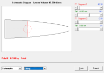
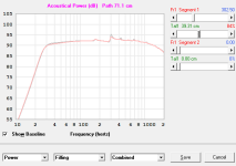
Tapered TL example.
How to understand Fr1 Segment 1 and tal1 practically?
Let's say I have 20-30mm sheep wool. Only overall stuffing weight matters?
Tapered TL example.
How to understand Fr1 Segment 1 and tal1 practically?
Let's say I have 20-30mm sheep wool. Only overall stuffing weight matters?
Attachments
Last edited:

Others might suggest too but as there is a little residual ripple, you could try incrementally adding fibre up to say 75% of the line length until you achieve an optimal response. you could build the enclosure using this amount and tweak to your listening taste or measurements. I found it needs a bit of iteration.
What I'm trying to do is smallest TL to reach 40Hz (30 litres) with stuffing or test with Fano-type silencer at the end of the line.
The TL design wizard give several different starting points. Using the MJK2021(A) as an example attached. You can play in the loudspeaker wizard with different values to see the effect of changes. The Brian Steele 2022 method looks nice but in a bigger box.


How to understand Fr1 Segment 1 and tal1 practically?
Let's say I have 20-30mm sheep wool. Only overall stuffing weight matters?
In the test example, 64% of the length of segment 1 (starting from the closed end) is filled with absorbent material having an airflow resistivity of 882.50 mks rayls/m.
METHOD 1 - Given absorbent filling material airflow resistivity and density data
A quick Google search reveals that the airflow resistivity of sheep wool varies greatly, depending upon the packing density:
Wool with a density of 10 kg/m^3 has a resistivity of 500 mks rayls/m.
Wool with a density of 100 kg/m^3 has a resistivity of 15000 mks rayls/m.
As a starting point, assume that the relationship between the wool density and airflow resistivity is linear so that for a resistivity value of 882.50 mks rayls/m the density is:
10 + (882.5 - 500) * (100 - 10) / (15000 - 500) = 12.37 kg/m^3.
The absorbent filling material in segment 1 has a volume of 32.148 litres [*] which means that the material weighs 0.40 kg if the density is 12.37 kg/m^3. The weight of 0.40 kg is a little less than the 0.518 kg shown for an equivalent volume of Polyfill, which means that the wool weight is probably about right given that it is likely to be less dense than Polyfill.
The simulation will show how the response is affected by adding filling material, but in practice the accurate flow resistivity value of the material being used is unlikely to be known. Most users just progressively add or remove filling material until the desired response as simulated is obtained.
[*] While the value is calculated and used internally, the volume of absorbent filling material in each segment is not currently displayed as an output. If it is not too much work to add, it will shown as an output in the next update.
METHOD 2 - Given Polyfill weight data only
Use the Polyfill weight as a starting point regardless of the actual absorbent material being used, and progressively add or remove filling until the desired response as simulated is obtained.
METHOD 3 - Given no absorbent filling material data
Progressively add or remove filling material until the desired response as simulated is obtained.
There was a guy named John Cockcroft who did a series of very stuffed transmission lines in Speaker builder magazine in the early 90's. I lost all of mine due to water damage. I have some back issues to look through.
I remember that he really stuffed them. Pretty much akin to mineral wool densities. If I remember the underlying mechanics you are slowing down the sound transmission speed through the fibrous tangle and effectively increasing line length.
Jacek you know my contact info if I can help.
Mark
I remember that he really stuffed them. Pretty much akin to mineral wool densities. If I remember the underlying mechanics you are slowing down the sound transmission speed through the fibrous tangle and effectively increasing line length.
Jacek you know my contact info if I can help.
Mark
Stuffing does not have a significant effect on the TL's Fb. A lot of stuffing in the box does severely reduce output at the vent however. It's no wonder that older so-called "classical" TL designs usually called for the use of drivers with higher Qts.
Right on all counts. I have a paper somewhere that actually measures vent output of a maximally damped enclosure. I will try a dig it up. There's never a free lunch. But there is making a driver to things better in different ways. The Speaker Builder articles were always using inexpensive Radio Shack drivers. So I'm guessing high Qts and weak motors. In effect a over grown variovent alignment.Stuffing does not have a significant effect on the TL's Fb. A lot of stuffing in the box does severely reduce output at the vent however. It's no wonder that older so-called "classical" TL designs usually called for the use of drivers with higher Qts.
Mark

Hi deanznz,
Thanks for the feedback. The Ra and Xa values should be as you say, so something is definitely wrong somewhere. The interesting thing is that the values for the test designs I checked are all correct. Could you please export the record you are using and post the data file here, so that I can replicate your results and hopefully track down the problem.
Kind regards,
David
If we hover over the vented box port details (Ap/Lpt) we get the air mass and end correction, and helmholtz mode freq, which is fantastic!
Is there a way to get that type of info displayed if using the upper section(S and L inputs ) so that tapered TL shapes, etc would yield similar info ?
thanks David
Is there a way to get that type of info displayed if using the upper section(S and L inputs ) so that tapered TL shapes, etc would yield similar info ?
thanks David
Last edited:
Could you please export the record you are using and post the data file here
No need to post the record thanks, I am pretty sure that I have found the problem - it will be fixed in the next update.
Just to be sure though, could you please confirm that your record uses stepped segments and/or is a CH2, CH3, OD2 or paraflex horn type configuration.
Is there a way to get that type of info displayed if using the upper section(S and L inputs ) so that tapered TL shapes, etc would yield similar info ?
Hi Bw,
Unfortunately, no.
The Ap and Lpt parameters specify the cross-sectional area and axial length of the cylindrical port tube in a bass reflex type loudspeaker, which is why it is possible to calculate the internal end correction and Helmholtz resonance frequency values.
A single segment or multiple segments could certainly be used to specify a "bass reflex port" in a front-loaded horn system, however Hornresp doesn't know that is what the segment is being used for, and in any event cannot calculate the throat end correction and/or Helmholtz resonance frequency for anything other than a cylindrical tube connected to a chamber.
While it is possible to calculate the air mass in a segment by multiplying the segment volume by the air density, I am not sure how useful that information would be in practice.
Kind regards,
David
Hi David, It is Not playing up today, I "think" I was using an OD record (on Con or Exp) then changed it to Nd when I noticed it was not reading correctly. I do Not think I was using stepped segments on that Record, but quite possibly on other records around the time.No need to post the record thanks, I am pretty sure that I have found the problem - it will be fixed in the next update.
Just to be sure though, could you please confirm that your record uses stepped segments and/or is a CH2, CH3, OD2 or paraflex horn type configuration.
I do have a low priority request, can the "Compare Captured" be applied to All graphs ? or have the option to be applied to all graphs.
cheers.
It is Not playing up today
Hopefully the changes to be made in the next update should fix the problem, one way or another.
can the "Compare Captured" be applied to All graphs ?
What are the charts that the feature is currently missing from?
As far as the loudspeaker wizard is concerned, pressing Ctrl+C when the power or pressure response chart is displayed captures the current results. Pressing Ctrl+V shows or hides previously captured results. Results for all loudspeaker wizard charts can in effect be captured by re-setting the baseline by pressing Ctrl+Alt+B.
can the "Compare Captured" be applied to All graphs ?
sorry I was not clear enough,
can the "Compare Captured" be applied to All graphs ? at once, instead of having to press F4 on each and every graph.
can the "Compare Captured" be applied to All graphs ?
If no unforeseen problems arise the functionality of the existing Compare feature will be modified in the next update so that selecting 'Compare Previous' / 'Compare Captured' / F4 will add the comparison traces to all six main charts, not just to the one currently being displayed.
Thought I'd write another thank you to David!
Here's a modelled vs measured comparison of a 1.72m exp horn path pair I'm building at the moment.
Test rigged in workshop - not ideal measuring space, but hey!

Note the bucket raisers.. give 26cm space for SPL to escape.

2.15m total height!
The modelled design, with driver, Eminence Kappa 12A.

The measured result

Not bad for a workshop measurement. I'm actually really pleased with this!
Performs exactly as modelled really.
This is with no XO just horn cutoff etc.
Cranked up test sweeps always seem soooo LOUD! Could probably try even louder but it drives the wife mad😂
More to come yet I think, as bracing, damping and backbox volume tuning is done.
I love Hornresp!
Here's a modelled vs measured comparison of a 1.72m exp horn path pair I'm building at the moment.
Test rigged in workshop - not ideal measuring space, but hey!
Note the bucket raisers.. give 26cm space for SPL to escape.
2.15m total height!
The modelled design, with driver, Eminence Kappa 12A.
The measured result
Not bad for a workshop measurement. I'm actually really pleased with this!
Performs exactly as modelled really.
This is with no XO just horn cutoff etc.
Cranked up test sweeps always seem soooo LOUD! Could probably try even louder but it drives the wife mad😂
More to come yet I think, as bracing, damping and backbox volume tuning is done.
I love Hornresp!
- Home
- Loudspeakers
- Subwoofers
- Hornresp