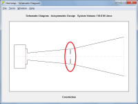
If you just want to model the bass component of the MEH system, independent of the output from the higher frequency drivers, then the general design you show is probably as close as you are going to get.
It shouldn't make a material difference but stepped segments could perhaps be used instead, to give something like the attached (not to scale).
An advantage of using stepped segments is that an additional segment becomes available to more accurately specify the overall horn profile, if so desired.
It shouldn't make a material difference but stepped segments could perhaps be used instead, to give something like the attached (not to scale).
An advantage of using stepped segments is that an additional segment becomes available to more accurately specify the overall horn profile, if so desired.
Attachments

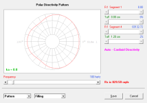
😳Given, the thickness is already calculated by the auto cardioid function.
And I missed this! Damn, double damn. Auto Cardioid. I am about to work on one of these!
Mark
For a given rayls value calculated by Hornresp, is there an algorithm/rule of thumb to convert it into a perforated board of given number of uniformly distributed holes and hole size?
Using iterative techniques it should be possible to come up with a solution at a single frequency, but it would be of little practical use.
For example, given:
Rs = 554.35 mks rayls
S1 = 500 cm^2
Tal1 = 0.8 cm
Hole diameter = 1 cm
Then the solution at 1000 Hz would be:
Hole centre to centre separation = 2 cm
hello @David McBean ,
I may have found a small bug or maybe just a (known?) limitation:
for any bandpass record whenever i change Xmax and Pmax in the driver parameter dialog box, then save the record, go to a previous or next record and switch back to the bandpass record Pmax is set to standard value of 100 W and Xmax to 5,0 mm.
is this a known limitation?
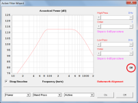
Hi David, I just upgraded to version 54.60 and the Filter Wizard has stopped functioning. The Filter Wizard window opens, but none of the parameters on the right side can be adjusted. Any suggestions?
Hi David,
Would it be possible to have a wavefront simulator that showed 2 or multiple horns with wave fronts from same input source exiting and overlapping/integrating?
Be able to change the timing of the wavefronts to demonstrate time alignment, say diaphragm point of origin and at point of exiting the respective horn mouths etc, vs non-alignment?
Could then model best horn placement / delays required in DSP controller to achieve.
Would help multi horn system building?
Just a musing really but perhaps has legs?
for any bandpass record whenever i change Xmax and Pmax in the driver parameter dialog box, then save the record, go to a previous or next record and switch back to the bandpass record Pmax is set to standard value of 100 W and Xmax to 5,0 mm.
Hi stv,
Thanks for the feedback, the changed values of Pmax and Xmax will be saved in the next update. Note however that the Maximum SPL feature is not included in the bandpass loudspeaker wizard, so that the saved values cannot be used anyway 🙂.
Kind regards,
David
The Filter Wizard window opens, but none of the parameters on the right side can be adjusted.
Hi Seth 001,
Double-click the Off label to switch on the Active Filter.
Kind regards,
David
Attachments
Hi Speedysteve7,
It can already be done - use the Custom Design option.
It can already be done - see the Wavefront Simulator section in the Hornresp Help file for details.
Kind regards,
David
Would it be possible to have a wavefront simulator that showed 2 or multiple horns with wave fronts from same input source exiting and overlapping/integrating?
It can already be done - use the Custom Design option.
Be able to change the timing of the wavefronts to demonstrate time alignment, say diaphragm point of origin and at point of exiting the respective horn mouths etc, vs non-alignment?
It can already be done - see the Wavefront Simulator section in the Hornresp Help file for details.
Kind regards,
David
OMG!!! That was easy. Thank you so much David, for everything!Hi Seth 001,
Double-click the Off label to switch on the Active Filter.
Kind regards,
David
Wow! Thanks David.Hi Speedysteve7,
It can already be done - use the Custom Design option.
It can already be done - see the Wavefront Simulator section in the Hornresp Help file for details.
Kind regards,
David
I will explore more.
I guess Hornresp is going mainstream now! lol 😀 😀
To bad he put the outlet in the front. Unless there is enough phase delay there will be some extraneous noises coming out of this port. I have never enjoyed the sound of a front ported system. To much midrange and upper bass comes through. You notice when it's absent.
Edit! Serves me right!
Port is on the back after all! Good work!
Mark
Edit! Serves me right!
Port is on the back after all! Good work!
Mark
Well, don't get me started on the design and driver choice lol 😀To bad he put the outlet in the front. Unless there is enough phase delay there will be some extraneous noises coming out of this port. I have never enjoyed the sound of a front ported system. To much midrange and upper bass comes through. You notice when it's absent.
Edit! Serves me right!
Port is on the back after all! Good work!
Mark
I've got access to two systems where there's so little out of band noise exiting the front port that I doubt anyone would be able to hear it. One of them is a 4th order BP system where the out of band noise is so low that it can be run without a LP x-over. The other is a cheap two-way system I purchased years ago.To bad he put the outlet in the front. Unless there is enough phase delay there will be some extraneous noises coming out of this port. I have never enjoyed the sound of a front ported system. To much midrange and upper bass comes through. You notice when it's absent.
About a year or so ago I put together a Hornresp model that described a vented alignment as an offset-driver, offset-vent two-stage stepped transmission line and noticed that the resonances through the vent can be significantly decreased by choosing a suitable location for the driver and the vent, and it turns out that the speaker had the driver and vent located in almost the exact positions suggested by the Hornresp model.
CORRECTION - Post #13,604
Rs (resistance) = 7.19 mks rayls.
My thanks to bolserst for making me aware of the error.
Zs (impedance) = 554.35 mks rayls.
Rs = 554.35 mks rayls
Rs (resistance) = 7.19 mks rayls.
My thanks to bolserst for making me aware of the error.
Zs (impedance) = 554.35 mks rayls.
It's one of those things that you may notice in it's absence. Kind of like high distortion in the bass. A lot of guys like it.I've got access to two systems where there's so little out of band noise exiting the front port that I doubt anyone would be able to hear it. One of them is a 4th order BP system where the out of band noise is so low that it can be run without a LP x-over. The other is a cheap two-way system I purchased years ago.
About a year or so ago I put together a Hornresp model that described a vented alignment as an offset-driver, offset-vent two-stage stepped transmission line and noticed that the resonances through the vent can be significantly decreased by choosing a suitable location for the driver and the vent, and it turns out that the speaker had the driver and vent located in almost the exact positions suggested by the Hornresp model.
I have always been able to pick up on nonlinearities in sound. same for ultra low frequencies. Don't know why it is.
Mark
Last edited:
Any chance you have that simulation to look at? You have me thinking a bit.I've got access to two systems where there's so little out of band noise exiting the front port that I doubt anyone would be able to hear it. One of them is a 4th order BP system where the out of band noise is so low that it can be run without a LP x-over. The other is a cheap two-way system I purchased years ago.
About a year or so ago I put together a Hornresp model that described a vented alignment as an offset-driver, offset-vent two-stage stepped transmission line and noticed that the resonances through the vent can be significantly decreased by choosing a suitable location for the driver and the vent, and it turns out that the speaker had the driver and vent located in almost the exact positions suggested by the Hornresp model.
Mark
Check the BOXPLAN-ODOV and BOXPLAN-VBSLOT workbooks available at the link: http://www.diysubwoofers.org/sheets/
The first one is an approximation (the Hornresp model is not quite exact, as the vent is inside, not outside, the enclosure).
The second one matches the Hornresp model exactly.
The first one is an approximation (the Hornresp model is not quite exact, as the vent is inside, not outside, the enclosure).
The second one matches the Hornresp model exactly.
- Home
- Loudspeakers
- Subwoofers
- Hornresp