
Thanks. I will try to apply your advice.your design looks just fine. In addition to trying out woodo's suggestions the only other thing I would probably do is to set the Path length parameter to an appropriate value
Hi,
when using the "TL Design..", all enclosures are "Closed mouth horns", the mjk-designes used to have an open mouth
in previous hornresp-versions i think.
I'm on version 54.50
when using the "TL Design..", all enclosures are "Closed mouth horns", the mjk-designes used to have an open mouth
in previous hornresp-versions i think.
I'm on version 54.50
Sorry, this happend after using a copy of a previous driver, using the default speaker all is normal(open mouth)
Two questions relating to TL design, Hornresp usage:
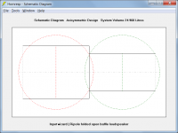
See attached sketch of five TL deisgns, bottom of sketch = floor, right side = towards wall, left side = towards listening room, top = towards ceiling.
1. Re. TL design: does exit location and direction (blue arrow) matter? If so, what is generally considered "optimal" and/or how would the 5 sketches differ in in-room response?
2. Hornresp usage: is the length of "path length" accurately shown by a) the red lines in the sketch? Or does this b) need to be calculated along the loudspeaker sides (i.e. 1 and 5 are correct, but 2,3,4 require red lines that follow along the edges of the loudspeaker) [EDIT: for my question #2, answer seems to be given here: To calculate the combined power output, the pressures, phases and physical separation of the two sources need to be known. For the purpose of the exercise, the loudspeaker enclosure itself can be considered to be "invisible". We are only interested in the straight-line distance between the two sound output point sources. If I interpret correctly, the red lines in my sketch accurately show path length).

Apologies if this has been asked before - I searched, but couldnt find answer (for example with "mouth location", never mind searching for "does exit location matter").
See attached sketch of five TL deisgns, bottom of sketch = floor, right side = towards wall, left side = towards listening room, top = towards ceiling.
1. Re. TL design: does exit location and direction (blue arrow) matter? If so, what is generally considered "optimal" and/or how would the 5 sketches differ in in-room response?
2. Hornresp usage: is the length of "path length" accurately shown by a) the red lines in the sketch? Or does this b) need to be calculated along the loudspeaker sides (i.e. 1 and 5 are correct, but 2,3,4 require red lines that follow along the edges of the loudspeaker) [EDIT: for my question #2, answer seems to be given here: To calculate the combined power output, the pressures, phases and physical separation of the two sources need to be known. For the purpose of the exercise, the loudspeaker enclosure itself can be considered to be "invisible". We are only interested in the straight-line distance between the two sound output point sources. If I interpret correctly, the red lines in my sketch accurately show path length).
Apologies if this has been asked before - I searched, but couldnt find answer (for example with "mouth location", never mind searching for "does exit location matter").
Last edited:
Two questions relating to TL design, Hornresp usage:
Hello clemenules
To find some useful information regarding how to model those TL, check the link below, click on the models TL and MLTL and you will find some colored scheme for the box, unfolded representation and hornresp System Model, it will help you better understand how to models those designs. You can download the FreeCAD models available or implement your own model using any CAD software. You can reverse engineering those models, it's not that hard, all information are easily accessible. I can create a new model for you if it's significant different from current models available.
Note: currenty models consider only the output sound (driver + vent/line) at the same direction.
https://freeloudspeakerplan.rf.gd
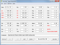
@David McBean Hello, I have some questions for you regarding Ripole Design....My PPSL with the back panel off is shaped as a Ripole, so far, its sounds pretty good in the room, likely due to the directivity. I cannot figure out how to Design it in HornResp to see whats going on.
I have 2 woofers in a slot, that is 20" deep....The rear of the woofers fire into rear side of the "ripole" baffle, and it extends 32".... Even this, I cannot figure out how to model in Horn Resp, is it possible? And if not would be possible to adjust Horn Resp to do so?
I have 2 woofers in a slot, that is 20" deep....The rear of the woofers fire into rear side of the "ripole" baffle, and it extends 32".... Even this, I cannot figure out how to model in Horn Resp, is it possible? And if not would be possible to adjust Horn Resp to do so?
@LORDSANSUI have you discovered any rear-facing exit backloaded horn TQWT designs worthwhile pursuing a build for?Hello clemenules
To find some useful information regarding how to model those TL, check the link below, click on the models TL and MLTL and you will find some colored scheme for the box, unfolded representation and hornresp System Model, it will help you better understand how to models those designs. You can download the FreeCAD models available or implement your own model using any CAD software. You can reverse engineering those models, it's not that hard, all information are easily accessible. I can create a new model for you if it's significant different from current models available.
Note: currenty models consider only the output sound (driver + vent/line) at the same direction.
https://freeloudspeakerplan.rf.gd
Last edited:
this happend after using a copy of a previous driver, using the default speaker all is normal(open mouth)
Hi rertrobaer,
Thanks for the feedback.
You have identified a bug which hopefully can be fixed in the next update.
Kind regards,
David
Re. TL design: does exit location and direction (blue arrow) matter? If so, what is generally considered "optimal" and/or how would the 5 sketches differ in in-room response?
As far as the power response is concerned, if the loudspeaker is suspended in free space (Ang = 4 x Pi steradians) then it doesn't matter where the exit port is located. If the loudspeaker is close to walls however, it will make a difference, depending upon the radiation impedance conditions applying at the port.
As far as the pressure response is concerned, the location of the exit port will affect the results in all cases, except in free space at very low frequencies, where the sound radiation is essentially non-directional.
The best position for the port is most likely to be as shown in your #1 option.
Hornresp usage: is the length of "path length" accurately shown by a) the red lines in the sketch?
Yes.
I have 2 woofers in a slot, that is 20" deep....The rear of the woofers fire into rear side of the "ripole" baffle, and it extends 32"....
I'm not exactly sure from your description how your system is configured, but Attachment 1 shows how to specify a Ripole loudspeaker in Hornresp.
Attachments
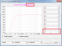
Hi folks - I am working on a TL for a SB Satori mid-woofer, and I've got nice flat extension in the bass, but a nasty
dip at 400-500Hz. I can't seem to get rid of this. Is it a sim artifact, or will my build have a big problem?
HR export attached.
BTW, thanks so much David McBean!

dip at 400-500Hz. I can't seem to get rid of this. Is it a sim artifact, or will my build have a big problem?
HR export attached.
BTW, thanks so much David McBean!
Attachments
hi @joetekubi, as far as i know (and I don't claim to know much!) this is immanent to a TL;
it is the cancellation effect of direct and delayed waves from the port.
you could try stuffing the first and eventually the second segment of the TL.
alternatively you might consider a mass loaded quarter wave resonator or anything between tapered and mass loaded.
also I know there have been solutions with a helmholtz resonator (absorber) tuned to the dip frequency located near the driver back.
Last edited:
Setting the “path” dimension I found in some cases helps with the apparent ripple.Hi folks - I am working on a TL for a SB Satori mid-woofer, and I've got nice flat extension in the bass, but a nasty
dip at 400-500Hz. I can't seem to get rid of this. Is it a sim artifact, or will my build have a big problem?
HR export attached.
BTW, thanks so much David McBean!
View attachment 1142842
Hi folks - I am working on a TL for a SB Satori mid-woofer, and I've got nice flat extension in the bass, but a nasty
dip at 400-500Hz. I can't seem to get rid of this. Is it a sim artifact, or will my build have a big problem?
HR export attached.
There will be internal resonances in any enclosure that has parallel walls. Perhaps do a little math and find out if your dip is related to a full, quarter or half wavelength of your enclosure. Frequency divided by the speed of sound. 450/340= 1.323 metres 52 inches, 26 inches. Your stuffing is not 100% absorbent. And Hornresp is one of the few simulation programs that will simulate internal reflections.
Mark
Setting the “path” dimension I found in some cases helps with the apparent ripple.
Attachments
Once the new Compound Horn proposal CHX is not going to happen, and I'm also thinking about another new one CHY, but it is not going to happen too for the same reasons so I'm just posting here to populate the wish list and let some history.
I can't resist the challenge of trying to squeeze yet more functionality out of Hornresp 🙂. I have started work on attempting to add the CHX and CHY options. It is a very big task and I am not sure how long it will take, if indeed it proves to be possible. If implemented, the new options will be called CH2 and CH3 rather than CHX and CHY.
Hi,
probably wine-related, so just for information and low priority, when cklicking
"File" -> "Editor...", it crashes with this message:

Also, whem importing a Hornresp-sim by "Import" -> "Hornresp Record", this only works
by typing the full name.txt, as the import-window is always empty, no matter what *.txt-files are in there.
probably wine-related, so just for information and low priority, when cklicking
"File" -> "Editor...", it crashes with this message:
Also, whem importing a Hornresp-sim by "Import" -> "Hornresp Record", this only works
by typing the full name.txt, as the import-window is always empty, no matter what *.txt-files are in there.
- Home
- Loudspeakers
- Subwoofers
- Hornresp