Hi Dwight,
There has been no change - still only a Microsoft Windows version available.
Kind regards,
David
There has been no change - still only a Microsoft Windows version available.
Kind regards,
David
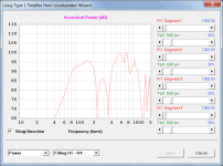
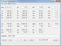
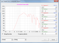
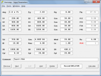
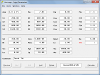
PH1 Paraflex Horn Model Validation
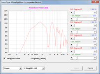
The results for a PH1 horn and its TH equivalent are effectively identical, confirming that the PH1 model is working correctly.
The results for a PH1 horn and its TH equivalent are effectively identical, confirming that the PH1 model is working correctly.
Attachments

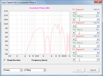
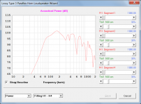
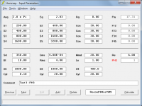
PH2 Paraflex Horn Model Validation
The results for a PH2 horn and its TH equivalent are effectively identical, confirming that the PH2 model is working correctly.
The results for a PH2 horn and its TH equivalent are effectively identical, confirming that the PH2 model is working correctly.
Attachments

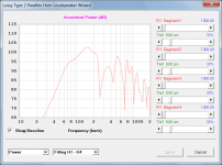

PH3 Paraflex Horn Model Validation
The results for a PH3 horn and its TH equivalent are effectively identical, confirming that the PH3 model is working correctly.
The results for a PH3 horn and its TH equivalent are effectively identical, confirming that the PH3 model is working correctly.
Attachments

PH4 Paraflex Horn Model Validation
The results for a PH4 horn and its TH equivalent are effectively identical, confirming that the PH4 model is working correctly.
The results for a PH4 horn and its TH equivalent are effectively identical, confirming that the PH4 model is working correctly.
Attachments

... Do you have a version that works on a mac? ...
As David said, it's a windows programm. But there are several ways to run it on a MAC.
- like mentioned above, you could use something using WINE.
- with bootcamp on Intel MACs, you could install a Windows in parallel to Mac OS
- You could install something like vmware fusion, paralllels or virtualbox (the later one being free) and install a windows and then run hornresp on it... A windows 7 licence can be bought for a few bucks from ebay. Reactos is free and runs windows programms, I once did a "windows free box" with hornresp and other simulation programms under reactos. Its footprint is very small, so a virtual machine in virtualbox with reactos takes up very little space and ressources.
Hello David et al,
Is it possible to change the coverage angle of a (front-loaded) horn in HornResp? For example, I'd like to simulate a 90x40 degree pattern.
Thanks, and thanks for sharing this utility with the world!
Is it possible to change the coverage angle of a (front-loaded) horn in HornResp? For example, I'd like to simulate a 90x40 degree pattern.
Thanks, and thanks for sharing this utility with the world!
hi,
I have tried to download hornresp but microsoft is blocking that.
why and what to do to complete the download!
I have tried to download hornresp but microsoft is blocking that.
why and what to do to complete the download!
Moving away from microsoft is a good start to fix the issue 😀
Just joking once I switched to Linux
Just joking once I switched to Linux
The MS download filter does sometimes block everythin it doesn`t "know" or what isn´t signed... You can simply add an exception to the security thingy of windows (make a folder, add that to the exception list in the security settings) and then do it again.
I'd like to simulate a 90x40 degree pattern.
The directivity model used in Hornresp assumes that the horn is axisymmetric. You would really need to use a finite element analysis program to obtain an accurate 3-D result for a rectangular horn.
Dwight, I just tried to get the Hornresp update, and the download fails for some reason? This is not the usual, so maybe there is a temporary server issue?
the download fails for some reason?
Just checked - it works fine for me.
How should this arrangement's throat be specified for a throat vented horn?
Hi David
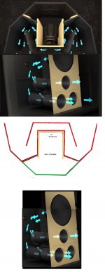
is the case of the new Klipsch Jubilee, there's a baffle board with 15 inch woofer and 3 duct ports "below" that woofer that fire into a flat panel then the expansion starts.
Knowing driver area, port area, baffle height, baffle width, and cross sectional details for the front horn, what area figure does one use for the throat?
Hi David
is the case of the new Klipsch Jubilee, there's a baffle board with 15 inch woofer and 3 duct ports "below" that woofer that fire into a flat panel then the expansion starts.
Knowing driver area, port area, baffle height, baffle width, and cross sectional details for the front horn, what area figure does one use for the throat?
Attachments
Just checked - it works fine for me.
Okay - it is working for me now, as well. (This was a failure during downloading; not the security warning you get when installing it.)
Hi David
is the case of the new Klipsch Jubilee, there's a baffle board with 15 inch woofer and 3 duct ports "below" that woofer that fire into a flat panel then the expansion starts.
Knowing driver area, port area, baffle height, baffle width, and cross sectional details for the front horn, what area figure does one use for the throat?
I very successfully modeled this for Volti Audio when I designed his LaScala variant. Hornresp modeled it very effectively. Sometimes as a direct overlay.
what area figure does one use for the throat?
Hi Freddy,
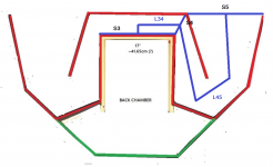
Having only segments 3 and 4 to play with, probably the best that you could do would be to set:
S3 (throat area) = mounting baffle height * mounting baffle width
S4 = 2 * angled width across duct at first bend * mounting baffle height
S5 = 2 * duct width at mouth * mounting baffle height
L34 = best estimate of axial length from S3 to S4
L45 = best estimate of axial length from S4 to S5
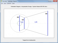
The horn would then have the general form shown in Attachment 2 (not to scale).
Kind regards,
David
Attachments
Last edited:
I very successfully modeled this for Volti Audio when I designed his LaScala variant. Hornresp modeled it very effectively. Sometimes as a direct overlay.
I missed the part to make this sensible.
When we measured the design many times the measurements and the overlays were nearly identical. When there were great differences it turned out that what was built was different from what was simulated. To mimmic the bifuricated design I would design a horn with the appropriate mouth area of one half of the enclosure. I modeled them together using the tools button then multiple speakers. There will be a difference in impedance and therefore SPL due to the choices of series or parallel for the driver impedance. But the overall response will be faithful
- Home
- Loudspeakers
- Subwoofers
- Hornresp