I'm thinking out loud...
If Sd = 531cm2 for a 12" driver and use:
Ap1 = 1,090.32cm2 (13in2),
Lp = 5.08cm (2in),
Atc = 531cm2,
Vtc = 1,011.56cm3 (531cm2 × 1.905cm),
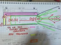
Could the throat chamber port be Segment Ap1A and Segment Ap1B for a 6 segment TH?
Would the BUILT model be accurate if S1-S2 was treated as the 3rd segment?
If Sd = 531cm2 for a 12" driver and use:
Ap1 = 1,090.32cm2 (13in2),
Lp = 5.08cm (2in),
Atc = 531cm2,
Vtc = 1,011.56cm3 (531cm2 × 1.905cm),
Could the throat chamber port be Segment Ap1A and Segment Ap1B for a 6 segment TH?
Would the BUILT model be accurate if S1-S2 was treated as the 3rd segment?
Last edited:
Is the C,E, and P keys available for Lp when using the TH function?
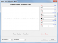
No. The tapped horn throat chamber port is cylindrical, with a cross-sectional area Ap1 and axial length Lp.
In the example I gave, the flared throat adaptor has an entry cross-sectional area Ap1 and an exit cross-sectional area S1.
Could the throat chamber port be Segment Ap1A and Segment Ap1B for a 6 segment TH?
Would the BUILT model be accurate if S1-S2 was treated as the 3rd segment?
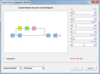
Not sure that I understand what you are getting at. You have specified a system as shown in the attachments, and it will be simulated as such. I guess if in Attachment 2 you choose to define TC as segment 1, TP as segment 2 and H1 as segment 3, then when you also include H2, H3 and H4 you have a 6 segment system in total, but it won't make any difference to the model or to the calculated results.
Attachments
Erro horn
Good morning Mr. Mc, I'm having trouble opening my Horn resp on W10, he's giving me an error like this (file / confg and won't open the program).
Good morning Mr. Mc, I'm having trouble opening my Horn resp on W10, he's giving me an error like this (file / confg and won't open the program).
I guess if in Attachment 2 you choose to define TC as segment 1, TP as segment 2 and H1 as segment 3, then when you also include H2, H3 and H4 you have a 6 segment system in total, but it won't make any difference to the model or to the calculated results.
Thank you DMB! That's EXACTLY what I was describing.
Half Ap1 x Lp = TC = S1-S2.
Half Ap1 x Lp = TP = S2-S3.
S1-S2 = H1 = S3-S4.
S2-S3 = H2 = S4-S5.
S3-S4 = H3 = S5-S6.
S4-S5 = H4 = S6-S7.
I asked because TC-TP needs to be an OD profile instead of a Nd profile.
I'm having trouble opening my Horn resp on W10
Hi Robson,
From your description, I am not sure what the problem could be, unless perhaps it is yet another anti-virus software false positive, in which case the post linked below might be of some help.
https://www.diyaudio.com/forums/subwoofers/119854-hornresp-1110.html#post6339240
Kind regards,
David
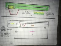
Can I stick and existing TL as shown in green, and place it in TH1 using VTC/ATC, Ap1/Lp and then create a lot of potential off set stub shapes at L12 and adjustable add on as a megaphone or large pipe segment with a constructed exit panel using L34 and L45? I’m looking to built a very versatile experiment and allow bolt on changes to an existing design without creating an unfair sim or cabinet to use as my laboratory. Stubs, waveguides and even mass loading might get looked at, added to the qw pipe section that is a solid performer already.
Using a lot of gasketed and machine screwed attachments to get a variety of results? I tried to avoid any ‘lump sum’ issues or complexities by using a simple TL to start. Only a slight offset as shown but kept it simple so it could be used to observe specific changes added or removed from it. will this be an issue or the use of VTC as an entire endfiring qw pipe going to be okay?
Hopefully not confusing, I realize the ideas are a bit unique or different...
Attachments
Last edited:
Help with learning horn simulation in python
Hello David,
I have recently completed a few beginner courses in Python, Pandas and Matplotlib.
I want to explore the possibility of simulating FLH using python and plot output using Matplot lib. Just using text editor and python interpreter or maybe Jupyter Notebook.
I seek your advise and wisdom on best point to start with and the optimal path to be taken.
Regards,
Giri
Can I stick and existing TL as shown in green, and place it in TH1
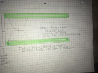
Your proposed design assumes that the driver can be located at S3, which is not correct.
I seek your advise and wisdom on best point to start with and the optimal path to be taken.
Hi Giri,
You will need to have a good understanding of horn theory, complex number arithmetic and network/circuit analysis to produce the required simulation model. The most comprehensive reference book available is "High-Quality Horn Loudspeaker Systems - History, Theory & Design" by Bjørn Kolbrek and Thomas Dunker. Other books containing information on horn loudspeakers are "Acoustical Engineering" by Harry Olson, and "Acoustics" by Leo Beranek.
Kind regards,
David
Your proposed design assumes that the driver can be located at S3, which is not correct.
There’s assumptions needed in a few areas, kind of tricky.
The wisest compromise for consistent use and abuse was to hopefully define and stick with the best assumed sim for the area from driver throat to driver mouth taps. Formerly just a qw pipe without a tapped mouth entry, now the minimum clearance for Pole vent and magnets considered as dual drivers in split or otherwise was looked at in order to keep the best simmable approach. I need to be able to show the results of change and in a few ways beyond the base qw pipe shape that is unchanged.
Hard to verbalize it type, as L45 is adjustable into larger and wider or even with a restriction window/ panel added, the L12 is adjusted to fine tune (absorber or not polyfilled versions) the use of L45. I’m Trying to show this to younger people to interest them in learning how to build the most interesting ideas they might have if opportunity or curiousity grabbed there attention. lately it seems this would help more than ever. Covid issues are becoming life issues or stress and a need to release it . Best to grab onto their young thoughts in a constructive way before anything else might? I think there’s a lot to see and explore in sim and real. that window is close?
Attachments
Hi Giri,
You will need to have a good understanding of horn theory, complex number arithmetic and network/circuit analysis to produce the required simulation model. The most comprehensive reference book available is "High-Quality Horn Loudspeaker Systems - History, Theory & Design" by Bjørn Kolbrek and Thomas Dunker. Other books containing information on horn loudspeakers are "Acoustical Engineering" by Harry Olson, and "Acoustics" by Leo Beranek.
Kind regards,
David
Thank you, David. I'll pursue that as a starting point.
Hornresp Update 5110-201011
Hi Everyone,
NOTE
This update was prepared on 11 October but the Setup.exe file could not be uploaded until 14 October due to difficulties accessing the host server. My sincere thanks to Sabbelbacke for investigating and solving the problem.
CHANGE
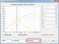
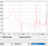
For systems with multiple outputs, a "Combined 1" option has been added to the loudspeaker wizard power response chart. When this option is selected, each separate output and the combined output are shown together on the one chart. Attachment 1 refers.
The "Combined 1" option is not included in the multiple entry horn loudspeaker wizard.
BUG FIX
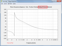
The following series of actions would cause the title of the Step 3 phase response comparison chart to incorrectly include time delay information, as shown in Attachment 2.
Step 1 - Calculate the phase response results for a given design.
Step 2 - Add a filter to the Step 1 results.
Step 3 - Compare the Step 1 and Step 2 results.
This bug has now been fixed, as shown in Attachment 3.
Kind regards,
David
Hi Everyone,
NOTE
This update was prepared on 11 October but the Setup.exe file could not be uploaded until 14 October due to difficulties accessing the host server. My sincere thanks to Sabbelbacke for investigating and solving the problem.
CHANGE
For systems with multiple outputs, a "Combined 1" option has been added to the loudspeaker wizard power response chart. When this option is selected, each separate output and the combined output are shown together on the one chart. Attachment 1 refers.
The "Combined 1" option is not included in the multiple entry horn loudspeaker wizard.
BUG FIX
The following series of actions would cause the title of the Step 3 phase response comparison chart to incorrectly include time delay information, as shown in Attachment 2.
Step 1 - Calculate the phase response results for a given design.
Step 2 - Add a filter to the Step 1 results.
Step 3 - Compare the Step 1 and Step 2 results.
This bug has now been fixed, as shown in Attachment 3.
Kind regards,
David
Attachments

There’s assumptions needed in a few areas, kind of tricky.
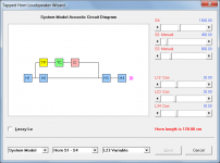
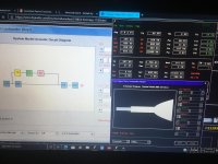
If in doubt as to how a particular "exotic" design specified in Hornresp will be interpreted by the program, simply check the System Model block diagram in the loudspeaker wizard.
Attachments
Hi David,Hi Everyone,
NOTE
This update was prepared on 11 October but the Setup.exe file could not be uploaded until 14 October due to difficulties accessing the host server. My sincere thanks to Sabbelbacke for investigating and solving the problem.
CHANGE
For systems with multiple outputs, a "Combined 1" option has been added to the loudspeaker wizard power response chart. When this option is selected, each separate output and the combined output are shown together on the one chart. Attachment 1 refers.
The "Combined 1" option is not included in the multiple entry horn loudspeaker wizard.
BUG FIX
The following series of actions would cause the title of the Step 3 phase response comparison chart to incorrectly include time delay information, as shown in Attachment 2.
Step 1 - Calculate the phase response results for a given design.
Step 2 - Add a filter to the Step 1 results.
Step 3 - Compare the Step 1 and Step 2 results.
This bug has now been fixed, as shown in Attachment 3.
Kind regards,
David
Awesome, as always. Do you plan to implement it in phase and group delay chart ? Since it can already be selected, but without effect 😛
Damien
Edit : nice curves colors 🙂
Attachments
Playing with the 4 curves of aperiodic bi-chamber enclosure with "combined 1" power chart is entertaining ^^
If in doubt as to how a particular "exotic" design specified in Hornresp will be interpreted by the program, simply check the System Model block diagram in the loudspeaker wizard.
I’m stretching some ideas likely, but kick me if needed:
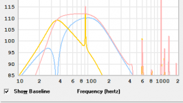
I have in TH1 used atc (Vtc)and Ap1/Lp (pink). H1 as L12 offset (yellow)the flow toward exit and before the driver motor side at s3(orange is L23).
Im fudging the 17cm and 5 cm shown and distributing it in a turn or vague area of s2 basically... my brain only sees it as vague, so I guess at the useful placement as it’s not perfect but I can move anything around to promote the sim accurate if there’s a better way? including the idea this is a pink qw pipe that’s permanent as it is. With a yellow poly fil preamp filter as L12 after it and then green and also adjustable as an acoustical amplifier and or bandwidth adjuster at L34/45 in TH1 throat Ported chamber mode.
That’s what I see if I tweet the L12 and L45, but it wasn’t until o failed to see it in wooden ideas originally
Attachments
Last edited:
I screwed this stuff up a lot in wood, so it’s not to hard to assume I’m off in this sim as well😀
Exploited version of L45 shown, filter needs to be skinny and/ or longer typically as well (polyfilled)
Exploited version of L45 shown, filter needs to be skinny and/ or longer typically as well (polyfilled)
Attachments
Last edited:
I've been modeling some FLHs. My 2015 version of Hornresp automatically calculates the delay in the horn path and applies this to the phase response however my 2020 version does not automatically calculate the delay. Is there a way to turn this back on?
Also which phase response is more accurate?
Thanks!
Also which phase response is more accurate?
Thanks!
- Home
- Loudspeakers
- Subwoofers
- Hornresp