Greets!
Been designing tower/column designs since the mid '60s and empirically learned that it's not a strong enough 1/4 WL resonator until it tunes a reflex/BR's alignment lower, i.e. need to shorten the vent to match it, which can sound a bit better damped, like when 'critically damping' the vent to remove any obvious 'ringing', but a true [constant taper] MLTL [by my definition] adds some obvious driver control like when a larger/longer vent is used on a BR except without the strong vent harmonics comb filtering with the driver's output [think Jensen Ultraflex/Onken 360].
In short, trading an oversize vent on a BR damped to 'taste' for a somewhat larger high aspect ratio cab with less damping + large, short vent for a net increase in efficiency/lower distortion, so by my definition many of the designs posted aren't MLTLs, but extended bass shelf alignments [EBS] in a high aspect ratio cab.
For instance, many of the MLTLs are 40-42" high after MJK's designs and once damped, quite smooth/extended, but IME it takes closer to 60" with Vas or larger net Vb to get the sort of damping/'heart attack fast' transient [horn like] response I prefer.
Many drivers today have extremely stiff suspensions [low Vas] that combined with a low Fs tuning, high power handling [Xmax] requires TL size/length vents to have a low vent mach, so better overall to morph this combo into an inverse tapered [ML] TQWT with 10:1 CR proving a good place to start simming and more often than not 'close enough', then fine tune with a vent 'stub' or learn compression horn theory if you want the best trade-off of size Vs gain BW.
Re the Tabaq, I've only looked at the original? with a really low tuning below Fs, so strictly a nearfield alignment IME and too high an aspect ratio, i.e. not enough cross sectional area [CSA] for its path-length to suit me, so based on what you've said, need to either increase it and/or add more damping to smooth it out........... or not as some of the sims I've seen look like a Rocky Mountain profile, yet folks claim a great performer, so just more proof that B0$3 was right, folks in general like their sound really 'rich' [audible harmonic distortion].
GM
This is brilliant!
When are you joining the various QW groups on the facebook? (not the "Facebook" part of FACEBOOK, but the rather specific nonsocial media type sections(like this forum essentially)). Your words of wisdom would be a WELCOMED addition to any of the handful (or less) of really good technical type QW ones.
Last edited:
For a variety of reasons, highly doubtful, though use to occasionally post on MJK's Yahoo Quarter Wave Group, but don't know [or care] if my membership was transferred to his Facebook Group and do occasionally follow MMJ's: High Order Quarterwave Society (DIY Paraflex & Super Planar dev community) Public Group | Facebook
GM
GM
For a variety of reasons, highly doubtful, though use to occasionally post on MJK's Yahoo Quarter Wave Group, but don't know [or care] if my membership was transferred to his Facebook Group and do occasionally follow MMJ's: High Order Quarterwave Society (DIY Paraflex & Super Planar dev community) Public Group | Facebook
GM
I understand, I have a lot of respect for your ideas and thoughts. I didn't know if those were around in other places, I've only seen you in MMJs that I know of. Another person I really enjoy reading and learning through.
--a question for horn Response:
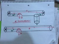
In the newer (2)closed end, offset port version of OD mode, a duplicate TL can be made and the port moved to the >normal< OD modes location at the end of the line path. This results in a phase shift at Fb, like the added closed end created the wave inversion as seen in this drawing were higher harmonic intervals maybe shown this better?
Or is the example shown just bass reflex action as the question is in regards to a cabinet made by a friend who wanted to know if this was in fact a TL(MLTL) as its a fullrange project and he noted a very clean sim in the upper bandwidth.
Attachments
Last edited:
The top pic looks BR to me. I wouldn't be surprised if both pics provide similar BR measured performance.
The top pic looks BR to me. I wouldn't be surprised if both pics provide similar BR measured performance.
If I rearrange it into the standard OD mode with only the port location offset adjusted it does almost dead nuts provide the same everything, except, phase angle at Fb is 180, not zero. Kind of interesting as it’s consistent with the two reversals if direction by the sound wave path to both closed ends and out. I’m likekybiver thinking that into something it’s not showing, but (?)
This new sim was interesting and while he didn’t take full advantage of the many things that dead end can become (stub, rez chamber, etc) he did note a lot of clean up in the higher bandwidth harmonics, and built a nice little cabinet with a hivi b4n tuned to 40hz with a tweeter from theat sim.
If I follow, the top one can be either a BR [assumes a ~uniform particle density] or an offset driver [OD] MLTL [has 1/4 WL pipe action, standing waves] depending on how high the aspect ratio relative to Fb, while the bottom one is an OD TL.
GM
GM
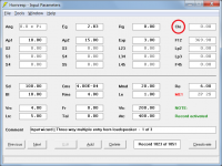
Hornresp Update 5080-200614
Hi Everyone,
BUG FIX 1
It was possible to specify a closed mouth on ME1 and ME2 records, and to open the multiple entry horn wizard when the Nd record had a closed mouth. See Attachment 1 for closed mouth ME1 example. These bugs have now been fixed.
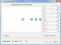
BUG FIX 2
On further testing problems were identified with several of the new system model acoustic circuit diagrams. See Attachment 2 for a typical example. These bugs have now been fixed.
Kind regards,
David
Hi Everyone,
BUG FIX 1
It was possible to specify a closed mouth on ME1 and ME2 records, and to open the multiple entry horn wizard when the Nd record had a closed mouth. See Attachment 1 for closed mouth ME1 example. These bugs have now been fixed.
BUG FIX 2
On further testing problems were identified with several of the new system model acoustic circuit diagrams. See Attachment 2 for a typical example. These bugs have now been fixed.
Kind regards,
David
Attachments
If I follow, the top one can be either a BR [assumes a ~uniform particle density] or an offset driver [OD] MLTL [has 1/4 WL pipe action, standing waves] depending on how high the aspect ratio relative to Fb, while the bottom one is an OD TL.
GM
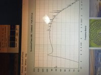
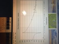
I got better details so I could sim it with a legit amount of accuracy. it appears to very much be a bass reflex by the upper regions lack of /\/\/\/\/\ implying any decent standing waves forming, and this has no stuffing to speak of. I'm assuming horn response only sees folding in as may segments as are filled in the user, but some sims dictate certain sections (L12, driver offset, for example) might dictate a driver position that might not fit as a turn in every design need/want so this is simmed pretty accurately as its a single fold at mid point and the middle section is split between L23 and L34. L45 is the segment after the port to exit.
the question I often hear is in regards to folding vs sim as many folks like t just use OD for a TL and L12, L23 are all that's entered, even if its shaped like a wooden snail😀😀
Attachments
Last edited:
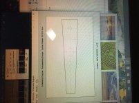
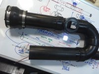
And this: probably what threw him off (or anyone) is the vaguely voight pipe or maybe TangBandqwt if I recall the shape used for those correctly (s1 is minuscule and expanding from there out to a s2 midway in the line length) like appearance of an expanding path to a round small port shape line but not grabbing the QW element here it would seem?
Attachments
Well, it's a high enough aspect ratio as shown with all the HF 'hash', just is so small for the tuning that it's effectively a BR in its gain BW.
GM
GM
Greets!
Been designing tower/column designs since the mid '60s and empirically learned that it's not a strong enough 1/4 WL resonator until it tunes a reflex/BR's alignment lower, i.e. need to shorten the vent to match it, which can sound a bit better damped, like when 'critically damping' the vent to remove any obvious 'ringing', but a true [constant taper] MLTL [by my definition] adds some obvious driver control like when a larger/longer vent is used on a BR except without the strong vent harmonics comb filtering with the driver's output [think Jensen Ultraflex/Onken 360].
In short, trading an oversize vent on a BR damped to 'taste' for a somewhat larger high aspect ratio cab with less damping + large, short vent for a net increase in efficiency/lower distortion, so by my definition many of the designs posted aren't MLTLs, but extended bass shelf alignments [EBS] in a high aspect ratio cab.
For instance, many of the MLTLs are 40-42" high after MJK's designs and once damped, quite smooth/extended, but IME it takes closer to 60" with Vas or larger net Vb to get the sort of damping/'heart attack fast' transient [horn like] response I prefer.
Many drivers today have extremely stiff suspensions [low Vas] that combined with a low Fs tuning, high power handling [Xmax] requires TL size/length vents to have a low vent mach, so better overall to morph this combo into an inverse tapered [ML] TQWT with 10:1 CR proving a good place to start simming and more often than not 'close enough', then fine tune with a vent 'stub' or learn compression horn theory if you want the best trade-off of size Vs gain BW.
Re the Tabaq, I've only looked at the original? with a really low tuning below Fs, so strictly a nearfield alignment IME and too high an aspect ratio, i.e. not enough cross sectional area [CSA] for its path-length to suit me, so based on what you've said, need to either increase it and/or add more damping to smooth it out........... or not as some of the sims I've seen look like a Rocky Mountain profile, yet folks claim a great performer, so just more proof that B0$3 was right, folks in general like their sound really 'rich' [audible harmonic distortion].
GM
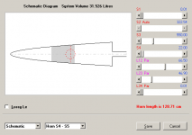
Thanks GM, but i only understand parts of your reply, tried even with google translate.
If i got it right, a MLTQWT would fit better, so i tried this with taper 1:20 with the same driver, see the attachments.
The vent is shorter/smaller diameter, which may work for levels suitable for my living room.
Does this shorter vent makes it more a ML or a BR enclosure?
Attachments
Well, it's a high enough aspect ratio as shown with all the HF 'hash', just is so small for the tuning that it's effectively a BR in its gain BW.
GM
I’m giving it the GM stamp of ‘approved’💪🏻. Bass reflex it is. The Aurorasound NS3 was going in here originally, last minute hivi change in what looks like coulda/shoulda been a pair of them.. ‘maybe he’s got another pair
Ii
FIX
- Download attachment
- Install font (micross.ttf) from attachment
- Change registry by clicking on file (Font Fix.reg) in attachment
- Restart pc and it works.
Thank you !
Thought?
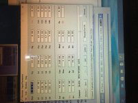
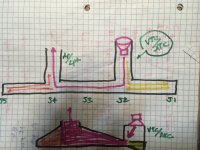
...and only that as it’s likely adding to an already full card, but in offset driver mode with ‘CLOsed’ selected can the user also be allowed to add an endfiring (VTC/ATC) driver entry segment at s2 maybe? This creating a length prior to s2 in pressure which a ‘stub’ or Rez chamber can be formed (using L12)
At s2? The idea is translated into these plastic pipe sections quick and easy via TS and capped ends at junctions...
Attachments
in offset driver mode with ‘CLOsed’ selected can the user also be allowed to add an endfiring (VTC/ATC) driver entry segment at s2 maybe? This creating a length prior to s2 in pressure which a ‘stub’ or Rez chamber can be formed (using L12) At s2?
I am not sure that I understand what you have in mind.
Would using OD1, Clo and stepped segments perhaps allow you to specify what you want?
Otherwise, it's another one for AkAbak...
I am not sure that I understand what you have in mind.
Would using OD1, Clo and stepped segments perhaps allow you to specify what you want?
Otherwise, it's another one for AkAbak...
I’m using L12 (yellow)and L45(Orange) as ‘chambers’ of various sizes and lengths that fall in different locations from driver to exit path(vent) and exciting different areas of bandwidth as they can be adjusted. With VTC/ATC the L12 chamber entrance from the driver is ‘downstream’ further. The bottom drawing is Similar to the actual shapes being chased in this and extreme versions of those are both filling the strange location for the subwoofer, but also trying to ice the flare whenever possible as an advantage.
Though if the offset port vent works in OD1, that is very useful in another way!
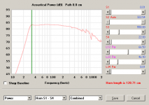
As you can see by the drawing, I’ve been hired by the US Navy to produce a submarine subwoofer, 😀 just kidding, of course, but the resulting shape does resemble...
Attachments
Could your drawing for your submarine woofer be considered an offset transmission line coupled with a helmholtz resonator? You might have to trademark that submarine name idea, I can see the advertising now! "Enjoy the low frequencies found only from THE DEEPEST Depths!"
Last edited:
Lol! I’ve got a blue nose and silver dolphins from the naval nuclear power program👍🏻 I think most guys might rather be inside a subwoofer box than a fast attack boat in the North Atlantic about March or so!🤢
Yeah, In some similar forms of this in TH mode the chamber as a rear vented from the other side of the cone where it clearly bumps response around the equivalent heimholtz Hz. Kindof like the ‘Roar’, I think, which is similar as well?
Yeah, In some similar forms of this in TH mode the chamber as a rear vented from the other side of the cone where it clearly bumps response around the equivalent heimholtz Hz. Kindof like the ‘Roar’, I think, which is similar as well?
Though if the offset port vent works in OD1, that is very useful in another way!
It doesn't work at the moment, but if all goes according to plan hopefully it will after the next update.
- Home
- Loudspeakers
- Subwoofers
- Hornresp