Subtracting one electrical impedance value from another does not give you the acoustical impedance loading the rear side of the driver diaphragm.
To add a bit detail to this: Seen from the electrical side, the driver looks like a parallel resonant circuit, see the diagrams on this page. The driver compliance appears as an inductance seen from the electrical side. Adding a closed box is equivalent to adding another inductance in parallel with the first one. As should be obvious from circuit theory, you cannot find the value of a parallel connected element in a circuit like this by simple subtraction.
To do the math, and ignoring Le and Rms to make it simpler, for the driver alone,
Ze1 = Re + 1/(1/((BL)^2*Cms) + (BL)^2/Mms)
and for the driver with box,
Ze2 = Re + 1/(1/((BL)^2*Cms) + 1/((BL)^2*Cab) + (BL)^2/Mms)
If you do the math, you will see that you cannot find Cab by subtracting Ze1 from Ze2.
Now I have to check if I can find the old screen shot. I may have a copy of Hornresp from away back 5 years ago. Gotta get to the bottom of this mystery.
Bjorn's program is pretty interesting isn't it!
@ David
OK I must be down wind of something hallucinogenic. I just ran the same input parameters on a version of Hornresp from a way back in 2013. I keep them all. And I get the same thing as the current version.
Must be confusing the measured parameters with the simulated parameters.
So now this leads me to the next question. I started digging around in scientific paper land to see if anybody else has found discrepancies with fibrous tangle calculations. And low and behold I'm not alone.
So my educated guess at this point is that a lightly compressed complete fill of a cabinet will be a totally different air resistivity than the single thickness measured and reported. It will not be a true doubling of each layer, but something a little bit more difficult to pin down.
A hunting I go!
Gotta get to the bottom of this conundrum. I'd like to be able to set up a more realistic simulation. And it's the old axiom, garbage in equals garbage out.
How did you survive the Cyclone in your area David?
Hi Mark,
Thanks for following up on this, you had me a little worried for a while 🙂.
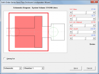
If you use the Clo option you can simulate as a filled chamber rather than as a lined chamber, as shown in the attachments.
The last cyclone that impacted on me in any way was Cyclone Joan, back in 1975. I was working in Port Hedland at the time. One interesting outcome was that my hire car had the paint on one side completely stripped off overnight by the wind-blown sand. Thankfully the damage was covered by insurance 🙂.
Cyclone Joan - Wikipedia
It is indeed.
Kind regards,
David
I just ran the same input parameters on a version of Hornresp from a way back in 2013. And I get the same thing as the current version.
Thanks for following up on this, you had me a little worried for a while 🙂.
I'd like to be able to set up a more realistic simulation.
If you use the Clo option you can simulate as a filled chamber rather than as a lined chamber, as shown in the attachments.
How did you survive the Cyclone in your area David?
The last cyclone that impacted on me in any way was Cyclone Joan, back in 1975. I was working in Port Hedland at the time. One interesting outcome was that my hire car had the paint on one side completely stripped off overnight by the wind-blown sand. Thankfully the damage was covered by insurance 🙂.
Cyclone Joan - Wikipedia
Bjorn's program is pretty interesting isn't it!
It is indeed.
Kind regards,
David
Attachments


Hi Mark,
Thanks for following up on this, you had me a little worried for a while 🙂.
If you use the Clo option you can simulate as a filled chamber rather than as a lined chamber, as shown in the attachments.
The last cyclone that impacted on me in any way was Cyclone Joan, back in 1975. I was working in Port Hedland at the time. One interesting outcome was that my hire car had the paint on one side completely stripped off overnight by the wind-blown sand. Thankfully the damage was covered by insurance 🙂.
Cyclone Joan - Wikipedia
It is indeed.
Kind regards,
David
Sand blasted car, well I guess that's one way of getting it done! May have created some frosted glass to. Not so conducive to driving!
The CLO option is pretty much the bees knees for this application. And again I get caught unawares of the potential of this program.
Thanks David!

What am I missing to get the options in the schematic page?
Hi Mark,
The Fr and Tal values specified on the main Input Parameters window apply to rear chamber lining only. When the Clo option is selected, a closed-mouth horn is in effect being specified. It is not possible to also have a rear chamber, because in that case, there would be no sound output from the loudspeaker system. This is why no rear chamber lining is shown in your schematic diagram (there is no rear chamber, only a cylindrical closed-mouth horn). With the Clo option selected, the Fr and Tal values can be set to zero if you like, as they are not used.
Open the loudspeaker wizard to specify the required filling material, which will then be shown in the wizard schematic.
Kind regards,
David
OK learning new tricks.
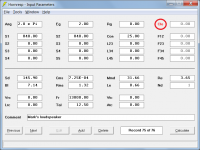
I can generate the correct filling in the loudspeaker wizard. And generate the lowered impedance in the loudspeaker wizard as you have shown. I cannot import the new filling into Hornresp proper like you would normally by pressing the save button. It is greyed out.
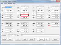
All in all pretty close to the measured results. A few ohms higher, but it always is. I'm guessing that the losses are not accounted for.
I cannot import the new filling into Hornresp proper like you would normally by pressing the save button. It is greyed out.
The Loudspeaker Wizard Save button is enabled when a slider value is changed. Filling values can be saved to the permanent record, but are only applicable in the Loudspeaker Wizard.
The Loudspeaker Wizard Save button is enabled when a slider value is changed. Filling values can be saved to the permanent record, but are only applicable in the Loudspeaker Wizard.
I figured out as much. Just verifying the function I was getting was correct. Pretty impressive. And accurate enough. Thanks again David.
Just verifying the function I was getting was correct.
Hi Mark,
Thanks for doing so - it keeps me on my toes, and sometimes uncovers a bug that needs fixing.
Kind regards,
David
Hornresp Update 4850-190101
Hi Everyone,
CHANGE
The ME delay slider limits in the Multiple Entry Horn Loudspeaker Wizard have been changed from +/- 100 cm to +/- 200 cm, as requested by Damien in Post #8958.
BUG FIX 1
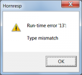
When the Resize Wizard was used with BP4 and BP6 records, a blank field would be inserted in the Lo1 input box, resulting in a fatal "Type mismatch" run-time error, as shown in Attachments 1 and 2.
BUG FIX 2
Under some circumstances there could be problems with the interactions between the Lc and Lo sliders in the BP4 and BP6 wizards, as shown in Attachment 3.
BUG FIX 3
Even if specified, acoustical lining was not being included in the rear chamber of a multiple entry horn system generated using the Input Wizard.
BUG FIX 4
The polarities of amplifiers 2 and 3 were always reversed when ME1 and ME2 records were imported into Hornresp, even if the polarities in the original exported records were normal.
These bugs have now been fixed.
Kind regards,
David
Hi Everyone,
CHANGE
The ME delay slider limits in the Multiple Entry Horn Loudspeaker Wizard have been changed from +/- 100 cm to +/- 200 cm, as requested by Damien in Post #8958.
BUG FIX 1
When the Resize Wizard was used with BP4 and BP6 records, a blank field would be inserted in the Lo1 input box, resulting in a fatal "Type mismatch" run-time error, as shown in Attachments 1 and 2.
BUG FIX 2
Under some circumstances there could be problems with the interactions between the Lc and Lo sliders in the BP4 and BP6 wizards, as shown in Attachment 3.
BUG FIX 3
Even if specified, acoustical lining was not being included in the rear chamber of a multiple entry horn system generated using the Input Wizard.
BUG FIX 4
The polarities of amplifiers 2 and 3 were always reversed when ME1 and ME2 records were imported into Hornresp, even if the polarities in the original exported records were normal.
These bugs have now been fixed.
Kind regards,
David
Attachments
Hi Everyone,
CHANGE
The ME delay slider limits in the Multiple Entry Horn Loudspeaker Wizard have been changed from +/- 100 cm to +/- 200 cm, as requested by Damien in Post #8958.
BUG FIX 1
When the Resize Wizard was used with BP4 and BP6 records, a blank field would be inserted in the Lo1 input box, resulting in a fatal "Type mismatch" run-time error, as shown in Attachments 1 and 2.
BUG FIX 2
Under some circumstances there could be problems with the interactions between the Lc and Lo sliders in the BP4 and BP6 wizards, as shown in Attachment 3.
BUG FIX 3
Even if specified, acoustical lining was not being included in the rear chamber of a multiple entry horn system generated using the Input Wizard.
BUG FIX 4
The polarities of amplifiers 2 and 3 were always reversed when ME1 and ME2 records were imported into Hornresp, even if the polarities in the original exported records were normal.
These bugs have now been fixed.
Kind regards,
David
Well this is impressive! Loking like a fair bit of bug swatting😉
Thanks David 🙂
Awesome work !
...but...new bug report
In ME wizard, double clicking on delay to switch from time to distance, or distance to time invariably gives value with unity of 2,12cm.
Thanks a lot David,
Damien
...but...new bug report
In ME wizard, double clicking on delay to switch from time to distance, or distance to time invariably gives value with unity of 2,12cm.
Thanks a lot David,
Damien
I seem unable to get the 1/f limit guideline or the Claus Futtrup limit
guideline to show on my group delay chart, using version 48.50. Are these still working or m I missing something? I've tried double clicking all over the group delay chart without success.
guideline to show on my group delay chart, using version 48.50. Are these still working or m I missing something? I've tried double clicking all over the group delay chart without success.
In ME wizard, double clicking on delay to switch from time to distance, or distance to time invariably gives value with unity of 2,12cm.
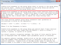
Hi Damien,
Double-clicking the delay caption automatically sets the slider to the actual physical path length difference.
For example, if the Nd record has Vtc = 10 cm3, Atc = 20 cm2 and L12 = 15 cm, and the ME1 entry point is at L12, then the distance from the Nd driver diaphragm to the 'nodal point' where the Nd and ME1 signals combine will be 10/20 + 15 or 15.5 cm.
If the ME1 record has total Vtc = 200 cm3, total Atc = 400 cm2 and Lp = 3 cm then the distance from the multiple ME1 driver diaphragms to the 'nodal point' where the Nd and ME1 signals combine will be 200/400 + 3 or 3.5 cm.
In this case, double-clicking the ME1 delay caption will set the slider to 12 cm (15.5 cm - 3.5 cm = 12 cm) which is the ME1 delay necessary to have the signals time aligned at the combination point. The slider can then of course be adjusted to a different delay value, if required.
Double-clicking on the delay value itself changes from distance to time in milliseconds.
Incidentally, the results produced by the Hornresp Multiple Entry Horn Model were recently independently validated by Dr Kolbrek, using other software, which is very reassuring indeed 🙂.
Kind regards,
David
Attachments
I've tried double clicking all over the group delay chart without success.
Hi jamesdb,
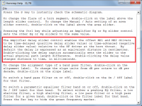
Make sure that you double-click the Y-axis vertical scale on the group delay chart, not the group delay per period chart.
Kind regards,
David
Attachments
Hmm, I'm thoroughly confused.........just installed 190101 and double clicking in 'group delay' pops up the 'sample' window, one click pops up the red line that displays frequency and delay and no amount of clicking anywhere gets me a green line or period chart.
GM
GM
Attachments
Last edited:
Hi David,Hi Damien,
Double-clicking the delay caption automatically sets the slider to the actual physical path length difference.
For example, if the Nd record has Vtc = 10 cm3, Atc = 20 cm2 and L12 = 15 cm, and the ME1 entry point is at L12, then the distance from the Nd driver diaphragm to the 'nodal point' where the Nd and ME1 signals combine will be 10/20 + 15 or 15.5 cm.
If the ME1 record has total Vtc = 200 cm3, total Atc = 400 cm2 and Lp = 3 cm then the distance from the multiple ME1 driver diaphragms to the 'nodal point' where the Nd and ME1 signals combine will be 200/400 + 3 or 3.5 cm.
In this case, double-clicking the ME1 delay caption will set the slider to 12 cm (15.5 cm - 3.5 cm = 12 cm) which is the ME1 delay necessary to have the signals time aligned at the combination point. The slider can then of course be adjusted to a different delay value, if required.
Double-clicking on the delay value itself changes from distance to time in milliseconds.
Incidentally, the results produced by the Hornresp Multiple Entry Horn Model were recently independently validated by Dr Kolbrek, using other software, which is very reassuring indeed 🙂.
Kind regards,
David
I agree this tool is awesome and used to work like a charm, but the error i talk about happens only with the last version.
I extensively use this tool since around maybe 2 years it exist, and have never experienced this. I cannot switch to time delay anymore with delay slider, no matter how many time i double click on "delay" ^^ Even with fresh records. It always give me some invariable values, always in cm.
Thanks,
Damien
- Home
- Loudspeakers
- Subwoofers
- Hornresp