Should it be possible to increase the amount of delay in ME wizard from +/-100 cm to let say +/-200cm ?
Hi Damien,
The delay slider limits will be changed, as requested, in the next update, due for release on New Year's Day.
Kind regards,
David
I was wondering if you could let me know what you think about venting into the horn closer to the throat or even in the front chamber. Is this generally just best avoided?
Hi Sugar Lion,
I suspect that in principle it is probably best avoided, but not having any experience with such systems, I am not really in a position to comment. Do your simulations show any advantages in using such a design?
Kind regards,
David
My gut tells me that having any type of hole in the early stages of the horn would be a bad idea. Seems like it would be safer further down the line where the pressure in the horn is lower.
Basically what you are describing is a 6th order bandpass design, with the "front" volume being vented by an expanding vent. It will be subject to the same advantages, i.e. you will be able to use a shorter vent to achieve the target Fb (the resonance is now affected by the mass of air in the horn). Also, with careful positioning of the vent along the horn's path, you could possibly null out the first "pipe resonance" associated with the vent. The only disadvantage I see is that the horn will also likely be amplifying the vent's pipe resonance modes.
I'd be tempted to try it, if I was looking to build such a thing.
Thank you very much for this. I will read it a few more times tomorrow when I am much more awake.
Hi Sugar Lion,
I suspect that in principle it is probably best avoided, but not having any experience with such systems, I am not really in a position to comment. Do your simulations show any advantages in using such a design?
Kind regards,
David
To be honest I have not gotten to that point yet. After your last post I was able to move forward in building the box for the driver and get the port in it. The port is not very long with my current design. About 7 inches. To get it into the 10+ inch area I was going to have to make the port about 2+ inches wide going by my calculations.
Right now it would be a 4.5l box with a 1.5" by 7" port being fed into an approx 1 yard long horn with a cutoff of about 250Hz. Horn comes next.
Anyone have advice of the best/easiest way to get from the Hornresp Schematic print out to a Wood plan layout?
Thanks everyone for your help! It makes a big difference.
Hi,
I just discovered the second-harmonic distortion information in the sample of 1 segment acoustical calcul. Can someone explain what it involve, how to use this ?
It change for example with my actual sim from 90db to 110db (for headroom) from around 0,005-0,01 to around 0,14%.
Thanks !
I just discovered the second-harmonic distortion information in the sample of 1 segment acoustical calcul. Can someone explain what it involve, how to use this ?
It change for example with my actual sim from 90db to 110db (for headroom) from around 0,005-0,01 to around 0,14%.
Thanks !
Can someone explain what it involve, how to use this ?
Google is your friend. Suggest you start with the search text string: second harmonic distortion in horns

Hi,
Bug report ?
I don't manage to make vented Chamber 1 and Chamber 2 working in multiple entry wizard, whereas it seems to work for Chamber 3 (ME2). Only Ap/Lpt from ME2 reccord appears and affect curve in ME wizard/and ME2 record.
Other verification :
_Ap/ Lpt from ME1 is not even taken in account in his own ME1 record (even in schematic). Verified inverting ME1 as ME2...Always only ME2 working as vented back chamber.
_Ap/Lpt is taken in account in Nd record when launched as non multiple entry, but no more in multiple entry wizard.
Sorry
Damien
Just to confirm with with fresh install, fresh records, on other computer, the problem is still there.Hi,
Bug report ?
[...]
And using 1 entry, Ap/lpt vent is only considered for ME1, not for chamber 1.
Bug report ?
Hi Damien,
Thanks for the feedback.
The following rules apply to the use of Ap and Lpt values specified in Nd, ME1 and ME2 records:
Two-way multiple entry horn system:
Vented rear chamber not applicable to high-frequency Nd driver
Vented rear chamber applicable to low-frequency ME1 drivers
Three-way multiple entry horn system:
Vented rear chamber not applicable to high-frequency Nd driver or mid-frequency ME1 drivers
Vented rear chamber applicable to low-frequency ME2 drivers
In other words, the only rear chamber that can be vented in a multiple entry horn system is that associated with the low-frequency drivers. This functionality is intentional, it is not a bug.
Kind regards,
David
Last edited:


Finding box only impedance?
.lets see what we can come up with here.
I can sweep a driver and do an impedance curve, no big deal.
Now i can sweep the driver and enclosure and get a different curve.
Question.
If i do a bit of math, ikr ew!
If i do some math can i safely say that when i subtract the driver impedance from the box/driver impedance that the remainder is the impedance of the box itself?
Im guessing if were going to be thorough you could do thr same with the box and driver in and out of the car.
Some things that occur to me
When in a box the resonance of a driver changes and may not be additive with box resonances...how to calculate this interaction if not simple math.
Is there a way hornresp can do this?
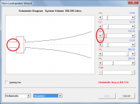
I thought i were able to play with vented Nd in mutiple entry, but i must have dreamed
Hi Damien,
You were definitely dreaming
.It is possible of course to play with a standard vented Nd horn system in the Loudspeaker Wizard, which is what I suspect you were probably doing.
Kind regards,
David
Attachments
When in a box the resonance of a driver changes and may not be additive with box resonances...how to calculate this interaction if not simple math.
Is there a way hornresp can do this?
The Hornresp does this automatically as part of the simulation.
If i do some math can i safely say that when i subtract the driver impedance from the box/driver impedance that the remainder is the impedance of the box itself?
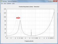
The measured electrical input impedances are different because the acoustical impedance loading the driver diaphragm has changed. Subtracting one electrical impedance value from another does not give you the acoustical impedance loading the rear side of the driver diaphragm. It is a bit like comparing apples and oranges.
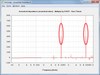
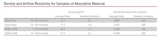
The closed box reacts on the rear side of the driver diaphragm. This reaction is represented as an acoustical impedance, which at low frequencies is a compliance operating to stiffen the motion of the diaphragm and raise the resonance frequency as shown in Attachment 1. At high frequencies, the reaction of the box, if unlined, is that of a multiresonant circuit. This is equivalent to an impedance that varies cyclically with frequency from zero to infinity, as shown in Attachment 2.
Attachments
A possible bug?
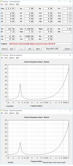
I did a set of simulations with this driver a few years back. The driver and system is in production and the impedance peak is just north of 10 ohms in real life. It used to simulate pretty close to that to. The enclosure is stuffed to the gills with properly cut and fit rockwool to create a maximally dampened enclosure. When I simulate it now with the same parameters it is not even close to the old simulation.
Hoping you guys are enjoying your holidays!
Attachments
When I simulate it now with the same parameters it is not even close to the old simulation.
Hi Mark,
Thanks for the feedback.
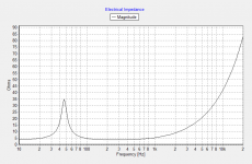
As far as I know, everything is working as it should. Just to confirm, I checked the Hornresp results against those generated using the program developed by Dr Kolbrek for his own use - see attached screenprints (acoustical lining material is included in each case).
I have no idea how you managed to obtain an impedance peak of around 10 ohms in your original Hornresp simulations using the input parameter values you show - it is a real mystery to me...
.Kind regards,
David
Attachments
Hi Mark,
Thanks for the feedback.
As far as I know, everything is working as it should. Just to confirm, I checked the Hornresp results against those generated using the program developed by Dr Kolbrek for his own use - see attached screenprints (acoustical lining material is included in each case).
I have no idea how you managed to obtain an impedance peak of around 10 ohms in your original Hornresp simulations using the input parameter values you show - it is a real mystery to me...
Kind regards,
David
Now I have to check if I can find the old screen shot. I may have a copy of Hornresp from away back 5 years ago. Gotta get to the bottom of this mystery.
Bjorn's program is pretty interesting isn't it!
- Home
- Loudspeakers
- Subwoofers
- Hornresp