These are coupled with the same driver?jzagaja said:Resulting CSD appended.

soongsc said:
These are coupled with the same driver?
Nope, and one is on a baffle, presumably, while the other is not.
Kick off the discussion here -- what do you see?
Magnetar said:The hole in the response according to the measurements gedlee posted is with in 30-40 degrees on axis, this is where the majority of the energy is and the most non linear part of the gedlee horn.
This was in response to my earlier post, so pardon me if you've realized this is not true by now. If you look at the provided data, the hole is just about gone at 7.5 degrees and gone at 15.
I'd also like to point out (and this is being a little pedantic), not just to you but to the others doing this, that in audio the term "nonlinear" almost exclusively refers to not obeying superposition... not, "not straight." What you are referring to (deviations from unity in the linear transfer function) is actually linear distortion.
Magnetar said:What's wrong with the manufactures plot? It doesn't have the Gedlee dip! Neither does my round tractrix horns - these probably sound excellent with a good driver like the Beyma Duke uses.
I agree with Dr. Geddes that these are normalized to 0 dB... i.e. on-axis is set to 0 dB in the plot. I don't see how you could argue this given the plot... they are all at 0 dB at 0 degrees. Also, it's difficult to read off "what the horn is doing" from polar plots like this because (1) the frequency domain resolution is poor and (2) EQing on-axis to be flat isn't necessarily the best solution. Also, no spatial averaging can lead one to believe that certain things are problems which aren't... but at least in that case the error is on the right side. All in all, I'd say the result is inconclusive... we need a better picture of what is going on to really judge what that horn is capable of.
FrankWW said:If the idea is as you say, then you will have a wide sweet spot.
Not necessarily... there is a distinction. You can make almost any speaker very flat on-axis by the use of extensive EQ, but it'll still sound like ****, because all of the reflections have different (and bad) responses (i.e. sweet spot is not equal to axis of flat response). You can also make a system that has a small sweet spot with speakers that are uniform in directivity- just use speakers like the ESP15 and aim them, say, straight ahead. Being only slightly off-center will widely skew the image (i.e. uniform directivity doesn't imply large sweet spot). What makes good tonality anywhere in the room is a speaker that has a smooth, flat response in every direction. What makes some place a sweet spot is the correct time arrival and amplitude of the original sound to ensure proper imaging.
ZilchLab said:O.K., let's all pretend that the direct sound from the speakers, whether that is coming from on their axes, or some off-axis angle thereof, is not of primary import. 🙄
The point of uniform power response is to insure that the secondary, reflected sound is similar in sonic character....
I don't understand what you're saying here. The direct sound is the most important of all axes, but the response at other axes is also crucially important... these are not contradictory statements. To put numbers on this, if I remember right, the Harman algorithm (presented at AES a few years ago) that was very good at correlating measurements with blind subjective impression (@ ~85 dB listening) weighted the listening window (spatial average +-30 deg horiz. and +-10 deg vert.) at about 40%... bigger than any other element but not the majority.
jzagaja said:Resulting CSD appended.
I have to wonder what use a CSD plot of an uneqed impulse response from one axis has. This is a very small piece of what these units are doing. It seems like the only way to get a feel for what the device is really doing is to look at the collection of impulse responses of many angles off-axis (say 10 degree increments horiz. and vert.) of the setup EQed for optimum response. Better yet, spatially average a bit (say listening window/early reflections/late reflections/power) and then IFFT and examine this collection of impulse responses.
Well I can't get the text file to work in Clio Damn I wanted to be able to set them up against CSD's I already had for some horns.
Rob🙂
Damn I wanted to be able to set them up against CSD's I already had for some horns. Rob🙂
Rybaudio said:
This was in response to my earlier post, so pardon me if you've realized this is not true by now. If you look at the provided data, the hole is just about gone at 7.5 degrees and gone at 15.
I'd also like to point out (and this is being a little pedantic), not just to you but to the others doing this, that in audio the term "nonlinear" almost exclusively refers to not obeying superposition... not, "not straight." What you are referring to (deviations from unity in the linear transfer function) is actually linear distortion.
I agree with Dr. Geddes that these are normalized to 0 dB... i.e. on-axis is set to 0 dB in the plot. I don't see how you could argue this given the plot... they are all at 0 dB at 0 degrees. Also, it's difficult to read off "what the horn is doing" from polar plots like this because (1) the frequency domain resolution is poor and (2) EQing on-axis to be flat isn't necessarily the best solution. Also, no spatial averaging can lead one to believe that certain things are problems which aren't... but at least in that case the error is on the right side. All in all, I'd say the result is inconclusive... we need a better picture of what is going on to really judge what that horn is capable of.
I am done repeating this - please look at the manufactures supplied graph!
If you are on axis then the hole is still there and 'great' within a 30 degree window- you fail to see the 7.5 and 15 degree plot - oh well! I think
MOST people listen to MOST speakers within a 30 degree window, but who cares anyway? I know I don't.
On the DDS, of course you can't see it 'all' from the manufactures plot, but at least I can see it is a much more competently designed horn then the gedleel horn - i certainly would take a pair of those for the same price as the gedleel horn, but the DDS is only 140 US a pair versus the gedleel horn at like 600 US 😉
Magnetar said:
No problem go on with your selling gedlee - I will just ignore you like I have in the past
Thats the best news that I have heard all day!! Thanks
Rybaudio said:
I have to wonder what use a CSD plot of an uneqed impulse response from one axis has. This is a very small piece of what these units are doing. It seems like the only way to get a feel for what the device is really doing is to look at the collection of impulse responses of many angles off-axis (say 10 degree increments horiz. and vert.) of the setup EQed for optimum response. Better yet, spatially average a bit (say listening window/early reflections/late reflections/power) and then IFFT and examine this collection of impulse responses.
I would certainly agree and would be willing to supply the data to do such a plot.
Magnetar,
Let me be super explicit. I count 13 responses. That corresponds to 7.5 degree increments from 0 to 90 degrees. Two of those, the dark blue and the purple, have a hole in the response. The dark blue, which I'm assuming is on-axis, has a large hole, while the purple, which I'm assuming is 7.5 degrees, is a much smaller smaller hole. The other responses are flat through this region. Are we not looking at the same plot? It is the last set on the PDF supplied. The next few responses, the green, orange, and light blue, are flat and even slightly upward tilted in the case of the orange and light blue.
The problem on-axis is easily avoided by using the aiming scheme, which is being used for an entirely different reason anyway (not a crutch for this alleged "problem"). Maybe there is something I am not seeing here but it seems pretty simple to me.
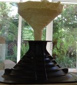
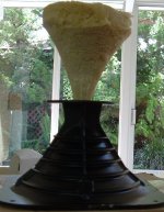
The horn looks like it has a quite even decay. The soft ridge between 1K~2K seems like the driver F0.ZilchLab said:
Nope, and one is on a baffle, presumably, while the other is not.
Kick off the discussion here -- what do you see?
The wave guide looks like some major resonances were suppressed using brute force method becasue it's decaying very fast in the beginning and at a certain level, it cannot decay as fast any more. The width of this longer tail in the CSD seems to suggest some for light acoustic loading causing the fast decay. Once the level is not as high, the acoustic loading is not as effective.
I cannot tell whether the characteristics are from the driving unit or the horn/guides, that's why I was asking.
gedlee said:DAH! Thats because they are all normalized to be 0 dB on axis!
One more reason to kindly lobby for a set of measurements for the DDS _similar_ to those you've done for the JBL.
🙂
Florian
soongsc said:
The horn looks like it has a quite even decay. The soft ridge between 1K~2K seems like the driver F0.
The wave guide looks like some major resonances were suppressed using brute force method becasue it's decaying very fast in the beginning and at a certain level, it cannot decay as fast any more. The width of this longer tail in the CSD seems to suggest some for light acoustic loading causing the fast decay. Once the level is not as high, the acoustic loading is not as effective.
Correct on both counts, assuming the Gedlee waveguide was measured with its foam plug in place.
Here's the spec sheet on the Selenium driver used on the JBL "horn":
http://www.seleniumloudspeakers.com/site2004/catalogo/pdf/D220Ti.pdf
I posted the impedance curve for that combination, as I measured it, the second attachment here:
http://audiokarma.org/forums/showthread.php?t=150939
I believe you have to register to be able to see the images. Tell them Zilch sent you.... 😉
I have measured many different compression drivers on the DDS waveguide.
On-axis, the DDS produces a broad dip from 6.5 kHz to 13 kHz. I'm looking at an un-equalized family of curves with 1/6 octave smoothing as I type this. This dip is present in every set of measurements I've made on this waveguide.
If this dip is depicted in the published polars, I sure as heck can't make it out.
Duke
Rybaudio said:I don't understand what you're saying here. The direct sound is the most important of all axes, but the response at other axes is also crucially important... these are not contradictory statements. To put numbers on this, if I remember right, the Harman algorithm (presented at AES a few years ago) that was very good at correlating measurements with blind subjective impression (@ ~85 dB listening) weighted the listening window (spatial average +-30 deg horiz. and +-10 deg vert.) at about 40%... bigger than any other element but not the majority.
I have to go with what Gedlee said on this issue @49
Image is very dependent on the direct field and the direct sound frequency response is critical.
Gedlee does not listen on axis; his prescribed speaker aiming pattern may not be a "crutch," but there's no denying that it explicity avoids the on-axis response anomaly inherent in the ESP waveguide design.
Frankly, I'm not here to debate the Gedlee waveguide, rather for the EconoWave measurement results, and as I view them, it's apparent that anyone can easily flatten the response of the JBL "horn" on axis using CD compensation and meet all of the criteria Gedlee specifies for good performance, better than the ESP waveguide, in fact, in both conventional and "unorthodox" alignments, the one exception being vertical dispersion, where the fact that it is a 50° vertical device, consistent with the Harman algorithm, has seemingly been ignored....
Waveguide or horn?
That statement surprises me a little (I use XT1086 currently, with a choice of drivers). In the narrow direction the profile near throat is certainly "waveguide like" (though not easy to measure accurately enough to be sure which function it follows). In the wide direction, however, there is a quite sharp change in the slope - somewhat "diffraction-horn like". 18sound photos of the device always seem to hide this feature, it is probably hard to photograph.
At the moment I don't have sufficiently good measurements to make them worth posting. The response is not too hard to equalise up to 10kHz, from 0 to about 45 degrees on the wide axis (as it happens I do use them toed-in considerably). Perhaps I'll have a go at better measurements, but it may take some time.
I've tried looking for HOMs but, although I thought I knew approximately what to expect from some crude FE modelling, I have not seen anything measurable (and am not sure what they sound like). But then I've not tried hard enough - no time.
Ken
gedlee said:The XT1086 looks like a very nice waveguide. It is basically an OS device.
That statement surprises me a little (I use XT1086 currently, with a choice of drivers). In the narrow direction the profile near throat is certainly "waveguide like" (though not easy to measure accurately enough to be sure which function it follows). In the wide direction, however, there is a quite sharp change in the slope - somewhat "diffraction-horn like". 18sound photos of the device always seem to hide this feature, it is probably hard to photograph.
At the moment I don't have sufficiently good measurements to make them worth posting. The response is not too hard to equalise up to 10kHz, from 0 to about 45 degrees on the wide axis (as it happens I do use them toed-in considerably). Perhaps I'll have a go at better measurements, but it may take some time.
I've tried looking for HOMs but, although I thought I knew approximately what to expect from some crude FE modelling, I have not seen anything measurable (and am not sure what they sound like). But then I've not tried hard enough - no time.
Ken
Magnetar said:No - I said they are round like the horn gedlee is selling but they sound fine on axis
Gee, thanks. That really helps. 🙄
I was asking a legit question. I tried tractrix horns but found them to be very peaky on axis. Sounds like the highs all beam down the center and don't spread out much.
Would like to know how other Tractirix work and sound, as it's a rather popular design. Sorry for asking....
panomaniac said:
Gee, thanks. That really helps. 🙄
I was asking a legit question. I tried tractrix horns but found them to be very peaky on axis. Sounds like the highs all beam down the center and don't spread out much.
Would like to know how other Tractirix work and sound, as it's a rather popular design. Sorry for asking....
They beam but on axis they are excellent- not peaky- you can use many of different sizes of them for different ranges, sit on axis, or refuse to accept the problem and use something else- I've done all three

- Status
- Not open for further replies.
- Home
- Loudspeakers
- Multi-Way
- Horn vs. Waveguide