I just looked at EZGPIB the other day. I have a Neutrik RT-1M I'm trying to talk (and listen) to over the GPIB. Multitone audio analyzer, should be fun to get it going.
But I have some hardware problems, looks like IRQ conflicts. All that legacy stuff is far from PnP!
Jan Didden
Edit: Sorry for OT. I'll shut up now...
But I have some hardware problems, looks like IRQ conflicts. All that legacy stuff is far from PnP!
Jan Didden
Edit: Sorry for OT. I'll shut up now...
Got a reply from MSI:
Group buy anyone?
Cheers,
Glen
Group buy anyone?
Cheers,
Glen
Hello Glen,
Pricing for less than 100 pcs of the MSSCSA is $7.25 each. The minimum
purchase order is $250 USD. If you would like a few pcs of the MSSCSA
for samples for evaluation, please let us know.
Thanks for your interest in MSI products.
Regards,
Jeff Thompson
MSI
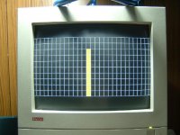
The prototype video generator is complete and working 100%. A photo of the screen is attached. With the design proven, all I have to do now is layout a proper PCB and assemble the finish product.
I have also updated the 20 second video:
http://users.picknowl.com.au/~glenk/VGAASA1.AVI
This time it is a little more exciting as I wired the potentiometer to two level bars inputs, so there are two level bars dancing on the screen this time in unison. Note that the flickering in the video is an artifact of the frame rate of my camera strobing with the frame rate of the SVGA monitor, and does not exist in real life.
The display will look much more dramatic when I have completed and wired in the 21 band filter/detector board, with all 21 level bars dancing on screen to music 🙂
Cheers,
Glen
Attachments

Okkaayyyy......
I have posted progress reports on this thingie from conception to the realisation of a working prototype.
Since I seem to be talking to myself for the most part, I’ll end it here. Anyone interested in the design can bookmark my website. I’m currently laying out the video generator PCB. Full design details will go up on my site once I have built and tested the final PCB to confirm and/or correct any errors made along the way (a few weeks at least)
A teaser shot of the video generator board schematic is attached below.
Cheers,
Glen
Attachments
Glen,
With 3527 views there seems to be a lot of interest. Why not note progress here once every few days?
Jan Didden
With 3527 views there seems to be a lot of interest. Why not note progress here once every few days?
Jan Didden
janneman said:Glen,
With 3527 views there seems to be a lot of interest. Why not note progress here once every few days?
Jan Didden
Jan, since you asked, not much to report until it's finished.
Here is the direct link anyway:
http://users.picknowl.com.au/~glenk/VGAASAMK1.HTM
The schematic links don't work yet, but I'm working on it.
Cheers,
Glen
Well now I’m just going to make myself look like a liar. However I’m just posting an update because things are progressing much quicker that I said they would.
If anyone is itching to get their soldering iron working, here is the complete video generator schematic. The band filter / peak detector board will follow on my website this evening.
Cheers,
Glen
If anyone is itching to get their soldering iron working, here is the complete video generator schematic. The band filter / peak detector board will follow on my website this evening.
Cheers,
Glen
An externally hosted image should be here but it was not working when we last tested it.
Glen,
Looks great! Presumably we can use this unit to look at the spectrum of a signal. Is there any way to bring this picture into a PC for documenting things? Is there a regular video signal that can be connected to a PC and stored?
A personal comment, not meant as a criticism: if the 'bars' would be narrower with some space between two adjacent bars, wouldn't that look more, ehh, professional?
Jan Didden
My compliments.
When "Byte" magazine first came out (must've been the late 1970's) Steve Ciarcia termed projects like this "software in solder".
When "Byte" magazine first came out (must've been the late 1970's) Steve Ciarcia termed projects like this "software in solder".
jackinnj said:My compliments.
When "Byte" magazine first came out (must've been the late 1970's) Steve Ciarcia termed projects like this "software in solder".
Remember 'Ciarcia's Circuit Cellar'? I think Glen took that over 😉 .
Jan Didden
Thanks for the compliments guys.
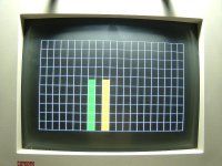
Jan, I originally had the graticule signal blanking the level bar video, producing a space between the bars, but then I decided that the white graticule looked better 😀
The display could only be imported by a computer with a video capture card that accepts VGA video. Don't know if such a thing exists.
BTW, I got held up with other things this evening so the filter board schemo isn't going to appear tonight. In fact, I'm about to got to bed (>10pm)
Cheers,
Glen
G.Kleinschmidt said:Got a reply from MSI:
Group buy anyone?
Cheers,
Glen
[/B]
Bump

Any other experimenters out there who would like to have a play with these fancy 1/6 octave filter IC’s? I only want 15 devices and would like to sell the MOQ excess, at cost of course.
I am currently finishing off the build of the 1/2 octave analyser and am starting to collect the bits for the much more advanced 1/6 octave CPLD based unit.
I'll be putting that one together after the next project on the list – the frequency sweeping / digital sampling unit that was the topic of this thread at the beginning.
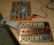
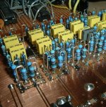
Anyway, today I finally finished loading the 21 band filter board and wired it into the video generator (still in rats nest prototype board form) and got the whole thing up and running.
Here is the coolest part - I have updated the video of the unit working in final form - The *.AVI file link again:
http://users.picknowl.com.au/~glenk/VGAASAMK1.AVI
In the video the analyser is connected to the audio output of a CD player, playing ‘Devils Dance’ by Metallica 🙂.
Full/finalised/tested circuit details of the half octave unit are now up on my Web page here:
http://users.picknowl.com.au/~glenk/VGAASAMK1.HTM
All I have to do now is etch/drill/load the PCB for the video generator and rebuild the unit, all neat and tidy into a 1U-rack case along with a power supply.
I intend to add a write up the circuit operation in the next week or so.
Here is what the video generator PCB looks like:
Top layer:
An externally hosted image should be here but it was not working when we last tested it.
Bottom layer (showing through top layer):
An externally hosted image should be here but it was not working when we last tested it.
Cheers,
Glen
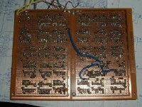
Oh, and the fully functional prototype as featured in the video:
Attachments
So it seems I am talking to myself again and nobody is interested in fancy SCF Ic's 
Did I mention that this revolutionary instrument can be used inspect at the visual level quantum absorption of phase incoherent nano crystalline junction diode audio signal modulation at the micro-molecular power level allowing the acutely open minded but scientifically astute audiophile to objectively evaluate and select with otherwise unattainable ultimate accuracy interconnects and speaker wires 100% consistent with the highest levels of sonic bliss permitted by the Galilean laws of Newtonian physics thus avoiding the subjective displeasure of hearing the finest symphonic orchestras reproduced with overstuffed mushroom like sonic stuffiness and mediocre pace rhythm and timing?
Anyway, here is a handy tip for anyone else who likes to layout PCB's for SMD but is then too much of a tight ar$e to add SMD parts to their stock/invertory:
Attachments
G.Kleinschmidt said:So it seems I am talking to myself again and nobody is interested in fancy SCF Ic's
Did I mention that this revolutionary instrument can be used inspect at the visual level quantum absorption of phase incoherent nano crystalline junction diode audio signal modulation at the micro-molecular power level allowing the acutely open minded but scientifically astute audiophile to objectively evaluate and select with otherwise unattainable ultimate accuracy interconnects and speaker wires 100% consistent with the highest levels of sonic bliss permitted by the Galilean laws of Newtonian physics thus avoiding the subjective displeasure of hearing the finest symphonic orchestras reproduced with overstuffed mushroom like sonic stuffiness and mediocre pace rhythm and timing?[snip]
... but it doesn't have hot and cold running water. Duhh.
But seriously, I for one am following this even if I didn't comment.
Sill not sure why I would prefer a dedicated unit over, say, a sound card and a s/w spectrum analyzer though.
How's your monster amp coming along?
And best wishes for 2009, not to forget!
Jan Didden
You haven't opened the floor to philosophical talk about transistor choices and connecting wire quality; no encouragement of topology discussion. How could there be any replies? 😀
Seriously looks mind bogglingly complex - I'm suitably impressed. 🙂
I do like the idea of a stand alone unit, dedicated to this rather than a computer and sound card. I generally use my "lab" computer to run Speaker Workshop, so I need to change the cables and settings and it become too much of a headache to run RMAA.
What would be the overall cost Glen?
- Status
- Not open for further replies.
- Home
- Amplifiers
- Solid State
- Homebrew Digital Sampling Audio spectrum analyser.