Hello Helmut,
The choke indicates 670 mA dc and 6 volts at 60cps so safer to use in a CLC supply.
My friend who uses the LL2771 connected in parallel to make a 700mH 2A choke for his 1A bias Hiraga stereo amp find out that once you go up to 2,5A the choke will not work.
Your choke is rated at 670 mA but at 60 hertz so at 50 hertz it will saturate at a lower level.
Especially for choke input the chokes are working hard. To make them work perfectly they need a minimum current flowing. The higher the mH number the less current you need to '' bleed with a resistor ''
Le monstre does not take that much current so it is not that difficult to make a proper choke input supply if you are willing to get a pair of chokes. With CLC choice of chokes will be broader.
Like i have written before my friends 20 watt Hiraga was recently upgraded from the original 200 mH ( French choke used in 50 watt Kaneda, you probably know that one!) to the the big Lundahl.
Greetings, Eduard
Eduard, as you can see, I didn't use the 0.66 A Choke for the L input, I used another one I had on hand, only 14 mH, but it works very fine, the other choke has its chance in a CLC configuration. But it fails.
Hello Helmut,
14 mH will not give you a supply that REALLY works as a choke input.
Suppose you would be using a 14-0-14 volt transformer with a true choke input the DC on the first capacitor after the choke will always be less than 14 volts dc. If it is above the choke does filter of course but not like it should do. You surely can notice an improvement but you will need more mH
If the 0,66 A is not an improvement compared to a resistor with similar dcr it is simply because it cannot handle the current so it will saturate and turn out to be inferior to a normal RC network.
I found similar chokes in my collection 2 mm diameter wire and a airgap. When there is not airgap they are probably meant to be used not in an amp like yours.
Of course things will improve after you reduced some cables where the transformer, rectifiers chokes and first caps are located.
Be prepared to get a bigger ( LL2771?) choke in the future. The Hiraga people tried a lot of stabilized power supplies but they always returned to the things we are using.
Greetings, eduard
So how do you calculate the correct size of choke.
Helmut diy speakers? they look a little like the old Ecouton
Helmut diy speakers? they look a little like the old Ecouton
Hello,
https://www.google.com/url?sa=t&sou...FjABegQIAxAB&usg=AOvVaw0lHPF-s1SUFTfcWpuWcJFJ
Hope this works. Here we have 50 cps so i calculate a bit easier.
Suppose you have 14 volts dc on the first cap.
Our friend Helmut will need 14/0,014H =1A minimum current before the supply starts working as a choke input. Usually this is done by installing a resistor across the first capacitor that will take care that there will always be this minimum current running before even connecting the amp itself.
Usually the current taken by the resistor should be much smaller than the one used by the circuit itself.
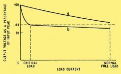
IF the current is not enough the supply will work as a capacitor input. In the yellow attachment you see the so called critical load that is the part of the load that needs to be take care of by the resistor. You can see after this minimum current a change of current will not affect the dc output as much.
The bigger the mH the lower current you need to waste by the resistor.
Nilton, my Brazilian pal, uses 700mH so he only needs to send 20 mA going down the resistor. So i think for a stereo le monstre amp you will need at least a 200mH 2A choke if you wanna go for a choke input one. The lundahl can be used for choke input , not all chokes can, some will buzz with 1,8 A even if they are specified for 3A.
The other attachment you see the specs of a rectifier tube. Here you also can see you need a certain inductance for the supply to work as a choke input. You can also see that with choke input the supply can deliver more current because the choke will cause a constant flow of current no charging pulses.
Greetings,Eduard
P.s with 60cps chokes can be a little smaller so above calculations are very safe
https://www.google.com/url?sa=t&sou...FjABegQIAxAB&usg=AOvVaw0lHPF-s1SUFTfcWpuWcJFJ
Hope this works. Here we have 50 cps so i calculate a bit easier.
Suppose you have 14 volts dc on the first cap.
Our friend Helmut will need 14/0,014H =1A minimum current before the supply starts working as a choke input. Usually this is done by installing a resistor across the first capacitor that will take care that there will always be this minimum current running before even connecting the amp itself.
Usually the current taken by the resistor should be much smaller than the one used by the circuit itself.
IF the current is not enough the supply will work as a capacitor input. In the yellow attachment you see the so called critical load that is the part of the load that needs to be take care of by the resistor. You can see after this minimum current a change of current will not affect the dc output as much.
The bigger the mH the lower current you need to waste by the resistor.
Nilton, my Brazilian pal, uses 700mH so he only needs to send 20 mA going down the resistor. So i think for a stereo le monstre amp you will need at least a 200mH 2A choke if you wanna go for a choke input one. The lundahl can be used for choke input , not all chokes can, some will buzz with 1,8 A even if they are specified for 3A.
The other attachment you see the specs of a rectifier tube. Here you also can see you need a certain inductance for the supply to work as a choke input. You can also see that with choke input the supply can deliver more current because the choke will cause a constant flow of current no charging pulses.
Greetings,Eduard
P.s with 60cps chokes can be a little smaller so above calculations are very safe
Attachments

Hi there,
Find more nice explanations about choke input...
Although a layman, it makes a lot of sense for me to have the choke at the filter input, since it has a high capacity to reduce ripple, attenuating the peak load and discharge capacitors.
For those who want to read the full study, follow the link:
LC Choke-Input Filter
Hello,
Sometimes our hobby is like physics education in high school. If you dont get it just get some other books on the same subject or have it explained by a class mate or another teacher and then suddenly you will see the light.
Nice things about chokes is they still work the same as they did a few decades ago. So consulting the Philips technical library, the BIG 1400 pages RCA handbook and you will find what you need to know.
Some chokes work better than other. When used for choke input differences are magnified. The 4 usual specs mentioned with chokes are inductance , current rating, dcr and maximum ripple. AND sometimes you will chokes designed for 400 or 800 hertz/cps that cannot be used in the designs here.
Most people fear using chokes with dcr on the higher side. My friends Hiraga improved on all aspects even the choke having a dcr of 2,8 ohm. My vietnamese friend use the 3,4 ohm ll2733 as choke input in his Nelson pass amp no problem.
Personally i dont know if going for a even bigger choke let us say 20 pounds 2000mH and 5 ohm dcr would be ok. Of course one can always try.
Of course this seize of choke could make a real big electronic flywheel but it could well be that the " garbage filtering power in higher frequency range " could suffer.
Greetings,Eduard
Rectifier
Hi Ed and Helmut,
Attached is the rectifier I will use in my Le Monstre project. I will try to solder its connectors directly to secondaries:
Ixys VBE 55-06NO7 https://www.tme.com/Document/f776475c315955e1b6f241c2f178e51e/VBE55-06NO7.pdf
Rgds
Nilton

Hi Ed and Helmut,
Attached is the rectifier I will use in my Le Monstre project. I will try to solder its connectors directly to secondaries:
Ixys VBE 55-06NO7 https://www.tme.com/Document/f776475c315955e1b6f241c2f178e51e/VBE55-06NO7.pdf
Rgds
Nilton
Last edited:
Hello,
Brazil Germany sounds like a soccer match!
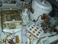
I found an image of that rectifier in actual use. It could well be possible to attach it directly to the transformers secundary side as i told Nilton to do.
This rectifier was recommended by a famous technician/audiophile in my country to use in my friends Hiraga . In the eighties the shop in Paris sold a rectifier to be used in the Hiraga. It had some specs that would make it stand out from the ones used usually. Probably similar to the one recommended here.
Of course using a rectifier in a power supply like used in a Hiraga would magnify differences between rectifiers.
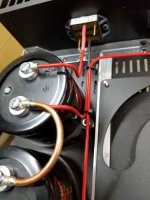
Helmuts connection right now looks like a birds nest so arranging them in the best way will surely bring some improvement because there are surely wires carrying currents that are disturbing nearby wires. Usually the biigest offenders are the ac wires and the wires carrying pulsating charging currents. These pulses will be reduced with a PROPER choke input. With 14 mH they could be reduced.
Of course mounting the rectifier directly onto the transformer is a perfect start to reduce wire length . As you can see in Helmuts pics the rectifiers would need additional heatsink. Maybe add a little one just to be safe.
Greetings, Eduard
P.s @ Helmut maybe we can agree on you trying trying a pair of 100mH 1,3A 1,3 ohm French chokes. If you wanna arrange something just send me a pm. They were made by the company that made the French EMT turntable ( called Bourdereau) There was one on ebay 8000 euro a few years ago
Brazil Germany sounds like a soccer match!
I found an image of that rectifier in actual use. It could well be possible to attach it directly to the transformers secundary side as i told Nilton to do.
This rectifier was recommended by a famous technician/audiophile in my country to use in my friends Hiraga . In the eighties the shop in Paris sold a rectifier to be used in the Hiraga. It had some specs that would make it stand out from the ones used usually. Probably similar to the one recommended here.
Of course using a rectifier in a power supply like used in a Hiraga would magnify differences between rectifiers.
Helmuts connection right now looks like a birds nest so arranging them in the best way will surely bring some improvement because there are surely wires carrying currents that are disturbing nearby wires. Usually the biigest offenders are the ac wires and the wires carrying pulsating charging currents. These pulses will be reduced with a PROPER choke input. With 14 mH they could be reduced.
Of course mounting the rectifier directly onto the transformer is a perfect start to reduce wire length . As you can see in Helmuts pics the rectifiers would need additional heatsink. Maybe add a little one just to be safe.
Greetings, Eduard
P.s @ Helmut maybe we can agree on you trying trying a pair of 100mH 1,3A 1,3 ohm French chokes. If you wanna arrange something just send me a pm. They were made by the company that made the French EMT turntable ( called Bourdereau) There was one on ebay 8000 euro a few years ago
Attachments
Hello,
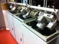
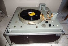
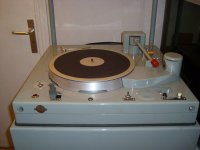
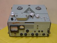
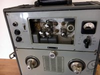
These are French turntables made by Bourdereau for the national broadcasting services in the sixties.
Back then there were a few French companies that made all the gear used in French studios. Bourdereau was famous for turntables and tape recorders.
You can see a studio version.
And the one they called portable.
They are extremely hard to find. They are made to last as you can see!
I just posted the pictures because some decades ago i came across 100mH chokes made by this company. Helmut, a respected member here, being influenced by the audiophiles in Paris might like these to be used in his Hiraga.
It is just wonderful gear to look at, i think very stylish, like a Citroen traction avant.
Greetings, Eduard
Attachments

Hello,
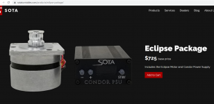
I needed a 24 volts dc supply capable of giving 500 mA continuously to power up a controller that will feed a BLDC motor for my turntable.
Most of the work needed to be done to make the motor run properly is done by the controller.
The power supply that the Americain company shipped to me was a 120 volts 60 hertz/cps one not one i can use here. It was a so called wallwart.
Usually these things are not made to last AND they are notorious for polluting nearby gear. SO i decided to make myself a better solution .
I reread some info that supported my ideas.
Greetings, eduard
Attachments
Hello,
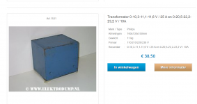
Maily for those in Europe i am giving the specs of the transformer i am using in a single rail power supply with choke input.
If you are willing to build an amp that also lloks like a Monster you could use two of these transformers. It has a static screen and was probably build to use in some kind of laboratory gear.
It indicates Philips Made in Holland probably made 40/50 years ago with cost no object '' viewpoint ''
Having two separate different secundairies it can be used for a Le Monstre with LCRC or CLC . Also possible to make a CLC supply for the 20/30 watt Hiraga
Greetings, Eduard
Attachments
Hello,
This thread is nearly dead. No need to blame it on corona or future economic meltdown. You dont need to actually build a le monstre to post something lol
Right now busy with a turntable power supply and designing a new pulley.
The motor housing has been ordered. Nearly 600 euro but will be made on a machine center with 5 axis that will need a replacement some day.
I just simulated a 30 volt pre regulation for a phono preamp
LCRC 16Henry 100 ohm 4700uF 220mOhm 10000 uF 120 mA load Ripple at the last cap well below 1 mV
Greetings, eduard
P.s Monday ordered at Mouser Texas USA . Parcel arrived in the Netherlands wednesday morning!
Good afternoon audiophile Gentlemen,
Permit myself to retain your attention and ask for help about the Jimsaudio PCB.
Like I am not a expert but only module builder, I can not understanding this le monstre PCB. See The attached picture.
I could not find the GND pointS for signal entry and signal exit. And too for the power supply .
Is it the « OV » point?
I thank you for your help and patience.
Best regards,
500px
Last edited:
Hello TYM,
I use this PCB, succesful. It is helpfull to have a closer look to the back of the PCB.
SG = Signal Ground. So you find your signal ground left beside the input.
Plus and Minus are made to solder spades into them, the same with the OUT and 0V. The last is for the center of your power supply. That is also the point for the MINUS of your output, I take it directly from my power supply. My Monster is dead silent, so it seemed to be not totaly wrong.
enjoy
Vielen Dank Helmut, It is nice of you.
If I well understand:
same ground point for the overall circuit:
OV= GND for : signal IN + signal OUT + power supply
Please, could you recommandate me about
power supply module and its capacitors
power transformer
I thank you really much.
Mit Freundlichen Grüssen
TYM
If I well understand:
same ground point for the overall circuit:
OV= GND for : signal IN + signal OUT + power supply
Please, could you recommandate me about
power supply module and its capacitors
power transformer
I thank you really much.
Mit Freundlichen Grüssen
TYM
Hello,
I just finished a replacement in one box instead of the two wallwarts that came with my new turntable motor. Because one of them was 120 volts 60 cps only and both had 6 feet output cables while i just need less than one feet and because two big lumps on my power outlet take to much space.
So i made a CRC 9 volt( R to create as little voltage drop) for the very basic 9 volt supply ( just used to feed the speed sensor).
An a better supply ( TPS7A4700 Ultra Low Noise Low Drop Out Voltage Regulator) instead of the flimsy SMPS supply as can be seen in the picture.
Both supplies i used with a split bobbin transformer.
A lot of these Chinese made supplies are using low quality parts allover. Even the copper wire is already tarnished compared to cables i have in stock for decades.
Greetings, Eduard
Attachments


- Home
- Amplifiers
- Solid State
- Hiraga "Le Monstre"