
Think about adding stoppers to the output transistors - they have a tendency to oscillate.
Shoog
Shoog
Think about adding stoppers to the output transistors - they have a tendency to oscillate.
Shoog
Can those be added directly over transistor legs?
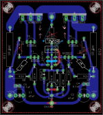
@sachu888, it seems you posted same image.
Last edited:
Can those be added directly over transistor legs?
@sachu888, it seems you posted same image.
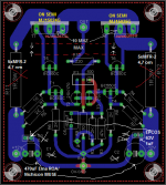
You are right,kindly ignore previous one.Here is the latest

Regards,
Sachin
Only if you use a resistor as a jumper from the base to the track.Can those be added directly over transistor legs?
@sachu888, it seems you posted same image.
Let me just add this is a precautionary measure - especially if the transistors have a higher bandwidth than the originals.
Shoog
You are right,kindly ignore previous one.Here is the latest
Regards,
Sachin
😀😀😀😱
Attachments
аnd change 1 om SQP resistor to 5*MFR-2 (4,7 om) 😀😀Thanks, I really appreciate it 😀
Regards
Sachin
аnd change 1 om SQP resistor to 5*MFR-2 (4,7 om) 😀😀
That would be Metal film,only footprint look different.Any specific reason for 4.7 Ohm value?
Regards,
Sachin
That would be Metal film,only footprint look different.Any specific reason for 4.7 Ohm value?
Regards,
Sachin
MFR-2 better than SQP, as example SQP 5% 300 ppm, MFR-2 1% 100 ppm. 5*MFR-2 4,7 om=0,94 om 10W. 😀😀😀😱
MFR-2 better than SQP, as example SQP 5% 300 ppm, MFR-2 1% 100 ppm. 5*MFR-2 4,7 om=0,94 om 10W. 😀😀😀😱
Thanks again 😉
Regards,
Sachin
аnd change 1 om SQP resistor to 5*MFR-2 (4,7 om) 😀😀
Thanks, does that mean 5 parallel resistance of 4.7 ohm MFR type.
Thanks, does that mean 5 parallel resistance of 4.7 ohm MFR type.
yes 😀
Only if you use a resistor as a jumper from the base to the track.
Let me just add this is a precautionary measure - especially if the transistors have a higher bandwidth than the originals.
Shoog
Got it thanks. You mean resistance on base of power transistors. Yes there could be one provision of some 1/4W resistance which could be 47ohm or so value. I have seen upto 470 ohm on base of fast transistors. If not used the it could be shortened with jumper.
I thought somebody mentioned 68pf on C-E of power transistor to stop oscillation.
Last edited:


Attachments
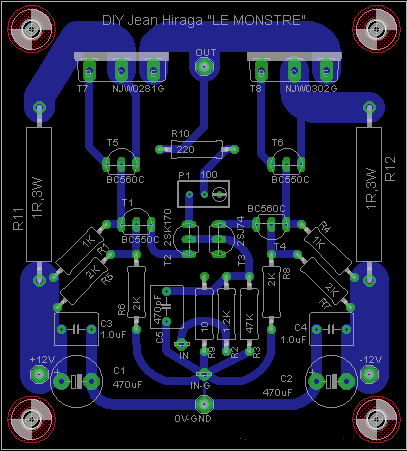
Thanks Demon for all your help.I really appreciate it 🙂
I have tried to include all suggested changes.This is final layout,no changes after this.I have changed the cap value to suggested 470uf,power resister not changed,but 5X MFR can be used at same place.We have decided to go ahead with NJW transistors because of cost and easy availability locally.
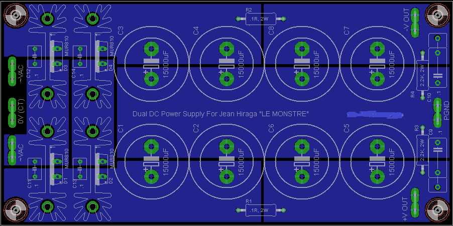
Suggested power supply design for one channel.Cap value is 15kuf 25V and can be increased if required.
Regards
Sachin
I have tried to include all suggested changes.This is final layout,no changes after this.I have changed the cap value to suggested 470uf,power resister not changed,but 5X MFR can be used at same place.We have decided to go ahead with NJW transistors because of cost and easy availability locally.

Suggested power supply design for one channel.Cap value is 15kuf 25V and can be increased if required.

Regards
Sachin
Thanks Demon for all your help.I really appreciate it 🙂
I have tried to include all suggested changes.This is final layout,no changes after this.I have changed the cap value to suggested 470uf,power resister not changed,but 5X MFR can be used at same place.We have decided to go ahead with NJW transistors because of cost and easy availability locally.
Suggested power supply design for one channel.Cap value is 15kuf 25V and can be increased if required.
Regards
Sachin
Resistor in CRC (2W 1 om) will blow up.
"We have decided to go ahead with NJW transistors because of cost and easy availability locally." And?.. In my shop too much TIP35C+TIP36C from ST, but I use ON Semi MJL on 4 MHz. 😀
With 30 MHz AMP will be unstable, look for MJW21192+91 as example, or another 4 MHz ON Semi.
I think PS has 0.1 ohm 2W. It would (except initial charging inrush) dissipate only <100mW as would constantly dissipate for <1A. IMO it would be barely warmer/indistinguishable from ambience temperature.
I think PS has 0.1 ohm 2W. It would (except initial charging inrush) dissipate only <100mW as would constantly dissipate for <1A. IMO it would be barely warmer/indistinguishable from ambience temperature.
need at least 5W resistor there.
If you want to stick with 2W resistor you have to use at least 3pc per side and adjust the value according.
Greetings
- Home
- Amplifiers
- Solid State
- Hiraga "Le Monstre"