Thanks Tazz,Damon for valuable feedback.
Regards
Sachin
To my ears the best sound with 85-120 om (instead 220 om resistor in feedback).
And don't use NJW3281+NJW1302 or another 30 MHz BJT (amp could be unstable) , better to set MJ15024+25, MJL21194+93 or MJL21196+95.
Last edited:
To use these 30MHz BJT you may want to add a compensation caps (ex. 68pF) across the drivers to keep the circuit from oscillating.
Rgds,
Eric
Rgds,
Eric
To use these 30MHz BJT you may want to add a compensation caps (ex. 68pF) across the drivers to keep the circuit from oscillating.
Rgds,
Eric
Of course, and the scheme "without Miller's Effect" will fall down to hell. 😡😀
I think that using correction is bad, that better to do Super Class A 20W/30W (the sound of scheme 20W is better than 30W).To use these 30MHz BJT you may want to add a compensation caps (ex. 68pF) across the drivers to keep the circuit from oscillating.
Rgds,
Eric
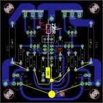
Thanks guys, I will post updated layout tonight. Any suggestion regarding power supply design?
Regards
Sachin
Regards
Sachin
Thanks guys, I will post updated layout tonight. Any suggestion regarding power supply design?
Regards
Sachin
CRC filter, 1F minimum, better to do 2,5F and batteries in buffer. Don't set leds on power supply of amplifier, resistor in CRC minimum 1 om, better 4 om. 🙂
Attachments
Use PSU2 to model it and see what you get at the output. You want the ripple to be less than 1mV which is a tall order indeed. You probably need more capacitance - but the good news is capacitance at these voltages is relatively cheap.
Shoog
Hi Shoog,
I did some simulation with PSUD2 and here are the results ;
Transformer +/- 12Vac output
35A bridge rectifier
CLC filter made from : 33000uF; 10mH, 5A; 33000uF
Output current 2A
Output voltage varies from 14.022 to 14.024V therefore 2mV ripple. 😀
other set-up using a CRC;
CRC filter made from : 33000uF; 0.1 ohm; 33000uF
Output current 2A
Output voltage varies from 13.98 to 14.07V therefore 90mV ripple. 😱
If I double the CRC to 68000uF, 0.1ohm and 68000uF the ripple only goes down to 30mV.
Why don't people use CLC filter ?? I must be missing something obvious...LOL
I will be using a CLC set-up for my Hiraga unless you guys do not recommend so.
BR,
Eric
CRC filter, 1F minimum, better to do 2,5F and batteries in buffer. Don't set leds on power supply of amplifier, resistor in CRC minimum 1 om, better 4 om. 🙂
I heard a friend's Hiraga that had 0.3F and it was an amazing amp. If you forget about the original Hiraga schematic would you really need to go to that extreme of using 1F-2.5F...+ batteries ? Just curious since capacitor back then were not as good as today's.
Can you actually hear the difference between a 1F and a 2.5F capacitor bank ?
Just trying to find out if this over designed power supply is really necessary for a 8W amp 😉
Rgds,
Eric

Did you hear 1F with batteries in buffer, then you would not be asking stupid questions. 😀I heard a friend's Hiraga that had 0.3F and it was an amazing amp. If you forget about the original Hiraga schematic would you really need to go to that extreme of using 1F-2.5F...+ batteries ? Just curious since capacitor back then were not as good as today's.
Can you actually hear the difference between a 1F and a 2.5F capacitor bank ?
Just trying to find out if this over designed power supply is really necessary for a 8W amp 😉
Rgds,
Eric
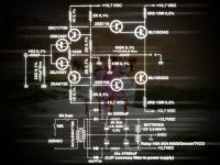
Before writing any crap - first look at the original power supply circuit Le Monstre 8W: The Class-A Amplifier Site - Hiraga 'The Monster' and The Class-A Amplifier Site - Hiraga 'The Monster' 😡😀😛
Attachments
Did you hear 1F with batteries in buffer, then you would not be asking stupid questions. 😀
Before writing any crap - first look at the original power supply circuit Le Monstre 8W: The Class-A Amplifier Site - Hiraga 'The Monster' and The Class-A Amplifier Site - Hiraga 'The Monster' 😡😀😛
I guess you had a bad day..LOL
I pity people with behavior like yours...keep your insult to yourself, I will not stoop down to your level.
Would the CLC I propose be OK for this amp ?
Peace man

Rgds,
Eric
Last edited:
I guess you had a bad day..LOL
I pity people with behavior like yours...keep your insult to yourself, I will not stoop down to your level.
Would the CLC I propose be OK for this amp ?
Peace man
Rgds,
Eric
Why 0,1 om, why no 0,01 om or 0,001 om?
Aaaaah, maybe you're blind and don't see on original sheme 4 or 8 om resistor in CRC. I repeat - "R", and maybe Hiraga was born in 15th century and didn't know: what's the "know-how" as inductive-capacitive?😀😀😀
It would be understandable using stabilizators, but using inductance... in analog power supply... I'm convinced that you like "castrated" sound.😉
Good luck.:Camoufl:
I guess you had a bad day..LOL
I pity people with behavior like yours...keep your insult to yourself, I will not stoop down to your level.
Would the CLC I propose be OK for this amp ?
Your avatar says "I'm only here to annoy you".
That's novel.
What is your amplifier question precisely?
Last edited:
but using inductance... in analog power supply... I'm convinced that you like "castrated" sound.😉
Good luck.:Camoufl:
I'm used to building great sounding tube amp which uses CLC filter.
Rgds,
Eric
Your avatar says "I'm only here to annoy you".
That's novel.
What is your amplifier question precisely?
Nice avatar, I know.
My question is simple ; Why do you need to use such an oversize capacitor bank, what is the real technical reason. The bias current is not high and the output power is only 8W. What would justify the use of so much capacitance...
Thanks for the help.
BR,
Eric
Did anybody tried it with reasonable valued capacitor bank, I mean towards smaller size?
I have built Pass F5 turbo v2 with each channel per rail it has 60,000uF within CRC as 30,000uF + 4 parallel .33ohm + 30,000uF. Still it was 200mV ripple for 3.5A bias. But after bias output offset was stable <10mV for 2-3hrs duration. Audibly perfect sounding amp surpassed everything compared with it.
So for 8W why we need overkill capacitor requirement?
Btw damon1983, thank you for the illustration.
; Why do you need to use such an oversize capacitor bank, what is the real technical reason?
Eric, I can't put my hands on my copy of L'Audiophile articles but I recall that these were a specific part of the design - I think to emulate the relative impedance of the 2A3 amplifier he was trying to match.
Ah - see The Class-A Amplifier Site - Jean Hiraga Index for the articles in French and (broken) English
This is the power supply he ended up with
An externally hosted image should be here but it was not working when we last tested it.
Yeah... Jean Hiraga = Maximum Current to the Load without Delays.😀
Eric, I can't put my hands on my copy of L'Audiophile articles but I recall that these were a specific part of the design - I think to emulate the relative impedance of the 2A3 amplifier he was trying to match.
Thanks for the explanation.
BR,
Eric
- Home
- Amplifiers
- Solid State
- Hiraga "Le Monstre"