Partly yes, partly No.
That's the first HIP4080 amp I've ever seen using both CD4013BE AND CD4069UBE. Usually it's just one of them.
That's the first HIP4080 amp I've ever seen using both CD4013BE AND CD4069UBE. Usually it's just one of them.
At this point, I can only say that you should not have any DC offset with the 1-2 bridge on the servo op-amp. The voltages on pins 6 and 7 should be very nearly identical. The op-amp voltage appears to be right since it's the same as the Zener voltage. The voltage on pin 6 appears to be the problem.
Is there a DC offset pot in the amp?
Is there a DC offset pot in the amp?
NO DC offset pot. Should I replace both CD4013BE AND CD4069UBE as this ones are feeding the pin 6 of the HIP4080 and they are pretty cheap and easy to find ?
I think I found a similar circuit (attached). Confirm.
http://www.bcae1.com/temp/Fusion-FP9001D caramp - 4080 like stealth.pdf
http://www.bcae1.com/temp/Fusion-FP9001D caramp - 4080 like stealth.pdf
Confirmed. Not exactly the same 1:1 as there is some slight differences in the used components but much much more similar than the hifonics schematics.
Until you told me that the 4069 was driving pin 6, I assumed that the other circuit was right. I'm not sure that this circuit will go to 0v offset with pins 1 and 2 of the op-amp bridged.
Does your amp have the equivalent of Q5?
Can you find the the equivalent of u9b?
Does your amp have the equivalent of Q5?
Can you find the the equivalent of u9b?
No Q5 transistor. No any BJT at all.
U9B is the same op amp we were doing the bridge 1-2 pins. NE5532. Pin 5 from the NE5532 goes through 2 resistors 100k and 1ohm, then directly to pin 18 of Hip4080.
Pin 6 of the same OP amp goes again through 2 resistors 100k and 1 ohm and directly into pin 12 of HIP4080
U9B is the same op amp we were doing the bridge 1-2 pins. NE5532. Pin 5 from the NE5532 goes through 2 resistors 100k and 1ohm, then directly to pin 18 of Hip4080.
Pin 6 of the same OP amp goes again through 2 resistors 100k and 1 ohm and directly into pin 12 of HIP4080
Last edited:
The B-channel of the 5532 is mixing the feedback from the two output terminals.
Does the 18v when you had 1/2 bridged swing to 1/2 rail plus 9v and 1/2 rail minus 9v?
With no bridge, was it swinging to rail and ground on the speaker terminals?
Does the 18v when you had 1/2 bridged swing to 1/2 rail plus 9v and 1/2 rail minus 9v?
With no bridge, was it swinging to rail and ground on the speaker terminals?
Does the 18v when you had 1/2 bridged swing to 1/2 rail plus 9v and 1/2 rail minus 9v? -
I didn't get that. When I bridge pin 1/2 it's straight DC of 18v between terminals, one of the speaker terminals goes to 45v dc and the other one to 27v referenced to main GND, even if feed signal to the RCA's.
With no bridge, was it swinging to rail and ground on the speaker terminals?
- with no bridge, no load i get nice sinewave as it should be once the voltage offset settle down.
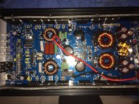
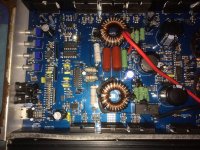
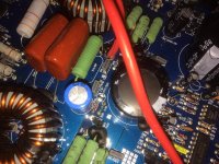
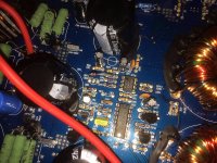
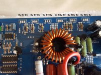
It's a shady amp...there's also missing components on the board right out of the factory, I know they may be not critical but still this does not inspire any trust.
I will attach some pictures.
I didn't get that. When I bridge pin 1/2 it's straight DC of 18v between terminals, one of the speaker terminals goes to 45v dc and the other one to 27v referenced to main GND, even if feed signal to the RCA's.
With no bridge, was it swinging to rail and ground on the speaker terminals?
- with no bridge, no load i get nice sinewave as it should be once the voltage offset settle down.
It's a shady amp...there's also missing components on the board right out of the factory, I know they may be not critical but still this does not inspire any trust.
I will attach some pictures.
Attachments
Last edited:
I should have been more clear in the first line. The first 1/2 was terminals 1 and 2. The second two 1/2s were one half of rail.
Does the 12v on the 4080 and pin 8 of the 5532 immediately go to 12v when the amp is powered up?
Does the 12v on the 4080 and pin 8 of the 5532 immediately go to 12v when the amp is powered up?
Does the 12v on the 4080 and pin 8 of the 5532 immediately go to 12v when the amp is powered up? - YES both does go immediately to 12v.
I'm sorry what is "TEO" ? U9 in schematics for the Fusion amp is 4 pre-omp amplifiers in my case there is only two (single NE5532) so there is only 8 pins ?
The equivalent of. I thought I had used it in this thread already.
The signal has to come from somewhere. What drives signal into the resistor that drives the inverting input of that op-amp (not pin 7 of the other half of the 5532)?
The signal has to come from somewhere. What drives signal into the resistor that drives the inverting input of that op-amp (not pin 7 of the other half of the 5532)?
Okay. I've fixed the amp and then by my stupid mistake in the late evening I've slipped the probe and killed one of the banks in the output section.
This resulted in a dead HIP4080 too.
So I've ordered new mosfets and HIP4080, but still i'm not sure if this is all i've killed in my lame mistake.
In the meantime while i'm waiting for the new parts to arrive, what i did was to remove all of the output mosfets and the HIP4080. Then I took measurements at all pins of the IC hip4080 while injecting 30hz sinewave thru the RCAs.
1-11.35
2-12.10
3-0
4-0
5-0
6-5.67
7- 8.10 - square wave 30hz
8-0
9-0
10-11.35
11-0
12- 5.67
13-0
14-0
15-12.10
16-12.10
17-0
18-0
19-5.67
20-0
Does this looks OK ? Is it safe to drop in new HIP4080 ?
Yes, when I slipped my probe i've shorted out one of the output mosfet in one of the output banks. This result in damaging one of the drive "channels" of HIP4080. Now instead of driving that bank properly, it sends out 8v DC. That's pin 11 if i remember correctly.
And the HIP4080 gets super hot in 15 second.
I have to stop working so late at night...
And the HIP4080 gets super hot in 15 second.
I have to stop working so late at night...
Hi again.
I've fitted new hip4080. Checked the gate drive at mosfets pads while injecting tone signal through RCA. It was there as a square wave.
Fitted new 4 mosfets irfz3710z one per bank for the test.
After a brief start they all got super hot and shorted out silently, killing again the hip4080 before I could turn of my power supply.
I had 15A inline fuse which is intact.
The amplifier is not valuable, it's not even a good amp, but i want to know what's wrong with it. The knowledge is what i care about. I want to know where my fault or incompetence is at.
These are the pad voltages across the output mosfet without the HIP4080. Should be there 6volts of DC at the source of bank 1 and the drain of bank 2 ?
Bank 3 and 4 from the other side of the amp are giving the same readings.
Attachments
- Home
- General Interest
- Car Audio
- HIP4080 based amp issues with DC offset (is it ?)