Okay, if i'm getting this right. Because this is full bridge class D amplifier, there is voltage on the - and + at the output terminals. And the sinewave swings in between 0v and rail voltage.
Both + and - speaker terminals sits at the middle of 0v and rail voltage. So if rail voltage is 60v, they will be at 30v.
Referenced to the main ground (GND), using 12v of B+input, there is +28v at +speaker terminal and +27,4v at the -speaker terminal. So there is ~ 0.6v offset.
Once I short pin 1 & 2 at the NE5532 there is:
37v at the +speaker terminal
19v at the -speaker terminal
So total of 18v DC offset between the + and - speaker terminals
I think the problem is that amp starts up with full rail voltage at + speaker terminal and sinks down to 28v, while the - speaker terminal starts at 0v and rises up to 27.4v. This causes a big issue if there is load at the speaker outputs and it takes like 15-20seconds to stabilize....of course this doesn't happen when I hook up a load, due to the fact this induces high current draw and crazy stuff at the output of the amplifier.
This equilibrium state at the speaker output + and - should happen faster, before even relay clicks in.
Last edited:
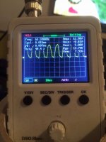
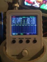
What's odd is that there is a triangle waveform on pin 6 that's biased to 6.5v and there is 6.5v DC on pin 7. That should give you the rail to rail oscillation.
Post the waveform and DC on pins 5, 6 and 7 of the 4080 with the jumper on the op-amp.
Post the waveform and DC on pins 5, 6 and 7 of the 4080 with the jumper on the op-amp.
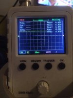
The IC is getting what it needs to produce good output. Pin 5 tells you what the internal logic is doing. The waveform should be more square but that could be due to the limited bandwidth of the scope.
Are you getting rail-rail oscillation on all 4 banks of output FETs?
Are you getting rail-rail oscillation on all 4 banks of output FETs?
Yes I do. I've seen test of this scope, reads pretty accurate to about a few Mhz.
Amps works just fine if i just wait 15-20seconds after relay clicks.
I have 4 pcs of IRF3710Z...this weekend i'm going to pull all of the B31N20D and replace them with the IRF3710Z (one per bank).
If this won't help, i'll order new hip4080 and replace it with ne5532 together
Amps works just fine if i just wait 15-20seconds after relay clicks.
I have 4 pcs of IRF3710Z...this weekend i'm going to pull all of the B31N20D and replace them with the IRF3710Z (one per bank).
If this won't help, i'll order new hip4080 and replace it with ne5532 together
I don't know if any of that will help.
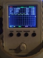
When you have 18v of offset, what is the duty cycle of the outputs on each side of the amp? Post waveforms.
When you have 18v of offset, what is the duty cycle of the outputs on each side of the amp? Post waveforms.

There are some inconsistencies. Previously, the duty cycle was 48%+. Here, it's 38%.
Using a multimeter and measuring the DC voltage from pin 4 of the op-amp to pin 6 and pin 7, when the voltage across the speaker terminals drops to (essentially) 0v, what is the voltage on those two pins?
I'm sorry to tell you but the scope isn't accurate, even at 65kHz. The waveform on pin 5 is going to be very nearly a perfectly shaped square wave. If the signal on the output FETs was as shown, the FETs would overheat and fail.
The difference in the waveforms from one bank to the other is due to an offset in voltage between the DC on pins 6 and 7.
DC offset goes as low as ~ 0.6v, does not drop to totally 0.
DMM for DC measurements, black probe (GND) on pin 4 of the OP amp red on pins 6 and 7.
NE5532:
pin 6 - 7v
pin 7 - 6.45v
HIP4080:
DMM black probe (GND) on pin 4 of the OP amp red on pins 6 and 7.
pin 6 - 5.9v
pin 7 - 6.05v
If I short pin 1 and 2 at the op amp ne5532 same measurements with (18v DC offset at the speaker terminals)
ne5532:
pin 6 - 7.2v
pin 7 - 6.9v
hip4080:
pin 6 - 5.9v
pin 7 - 6.45v
6/7 of the 5532 aren't important with pins 1/2 shorted.
Does the waveform on terminal 6 of the 4080 immediately go to 5.9 and settle there?
What's the DC voltage on the equivalent of (TeO) ZD1C?
If you remove TeO C20A and the 1/2 jumper, do you still have the initial offset problem on the output?
Does the waveform on terminal 6 of the 4080 immediately go to 5.9 and settle there?
What's the DC voltage on the equivalent of (TeO) ZD1C?
If you remove TeO C20A and the 1/2 jumper, do you still have the initial offset problem on the output?
Does the waveform on terminal 6 of the 4080 immediately go to 5.9 and settle there?
- Yes, it does immediately
What's the DC voltage on the equivalent of (TeO) ZD1C?
- 11.35v (i'm not sure this has to be that high, this amp also uses lm393)
If you remove TeO C20A and the 1/2 jumper, do you still have the initial offset problem on the output?
- Yes sir, still the same.
- Yes, it does immediately
What's the DC voltage on the equivalent of (TeO) ZD1C?
- 11.35v (i'm not sure this has to be that high, this amp also uses lm393)
If you remove TeO C20A and the 1/2 jumper, do you still have the initial offset problem on the output?
- Yes sir, still the same.
My bad due to a little different layout between the schematics and the amp itself.
It's 6.45v. There is a film cap between ZD1C and the R17C.
It's 6.45v. There is a film cap between ZD1C and the R17C.
Pin 7 from 393 goes through two 2k resistors to pin 4 of CD4013BE which datasheet says it's reset 1.
Also pin 1 from 393 is in direct short with the same pin 4 of the CD4013BE
Also pin 1 from 393 is in direct short with the same pin 4 of the CD4013BE
Attachments
Last edited:
It's pin 1 from the cd4069ube - through 2 resistors.
Wave and voltage is the same at the cd4069ube at pin 1 and pin 6 at hip4080.
Wave and voltage is the same at the cd4069ube at pin 1 and pin 6 at hip4080.
- Home
- General Interest
- Car Audio
- HIP4080 based amp issues with DC offset (is it ?)