Their big disadvantage is nobody knows them here. Without a supporting community you are lost.Boardmaker 1,2,3 has a huge advantage over all other programs:
I know that fact 😢.
The problem is more of a academic nature, for this mini circuit you /we can certainly evaluate any layout program. But merging D into X should not actually be a hurdle at all, after all, this arrangement has been functioning for a good half century.
The scenario reminds me more of the fact of German (or international) incompetence in matters of repair service for our automobiles:
An example could be, "since our diagnostic connector or the latest software update is no longer compatible with your SuperDuper DSG, we are unable to change your wheels."
Sorry, this is offtopic.
Last edited:
Tim's first circuit board
Everything your heart desires: converted and stored here as SprintLayout6 files. The *.zip now contains the PCB in modern form as *.lay, *.ps, *.gbr, *.drl and there should now be no problems with further editing.
Perhaps someone would like to create an assembly print 😉.
Have fun,
HBt.
Everything your heart desires: converted and stored here as SprintLayout6 files. The *.zip now contains the PCB in modern form as *.lay, *.ps, *.gbr, *.drl and there should now be no problems with further editing.
Perhaps someone would like to create an assembly print 😉.
Have fun,
HBt.
Attachments
Class Bernhard 🙂.
Approximately similar, but only just under 10mA each through the VAS branches.
thx
Q1,Q2,Q3,Q4 plus N1,N2 should (finally) all be immersed together in a small aluminum body (to be made), add some thermally conductive paste.
Under no circumstances should the quiescent current through Q1 & Q2 be greater than 10mAdc ... the common RE= (10Ohm/3) is far too small to have a stabilizing effect ... This is one of the imponderables of this stage. It may be necessary to replace N1 and N2 with other types or, or, or ...
The power supply to the output stage is unregulated and separate from the pre-stage (in reality!).
The 5mAdc sink is already rudimentarily implemented on the circuit board.
#
Dear Bernhard,
I think it's great that you decided to feed MicroCap12 with the circuit after all - brilliant.
Thank you
Last edited:
So the 5mA now should be a ccs?
I removed it in my schematic and the resistor was as good as the ccs.
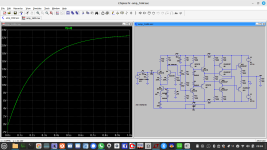
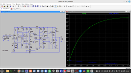
Also I simulated your schematic already. 4mA, 5mA, 6mA - doesn´t matter.
And, the ccs doesn´t help either.
Same with 3.3k and 3.3 ohms.
Different idle currents still show the same result.


I removed it in my schematic and the resistor was as good as the ccs.
Also I simulated your schematic already. 4mA, 5mA, 6mA - doesn´t matter.
And, the ccs doesn´t help either.
Same with 3.3k and 3.3 ohms.
Different idle currents still show the same result.
Note:
Under no circumstances
For me personally, a little PowerAmp has to follow the KISS or economy principle.
I hope many readers will feel encouraged to think through the circuit and size it successfully. Practical results from my side will not be available for a few weeks.
Anyone who would like to ask questions now is encouraged to do so.
Now that a model for MC12 is available, @Bernhard can already put the design proposal through its paces in the computer and sound the alarm if something could go seriously wrong.
regards,
HBt.
Under no circumstances
- should it be assumed at this stage that the circuit shown here has already been tested in practice and finally dimensioned
- will I be able to etch or mill the two test boards before the coming weekend, i.e. 14 days will certainly pass before I can contribute real results to the test setup.
For me personally, a little PowerAmp has to follow the KISS or economy principle.
I hope many readers will feel encouraged to think through the circuit and size it successfully. Practical results from my side will not be available for a few weeks.
Anyone who would like to ask questions now is encouraged to do so.
Now that a model for MC12 is available, @Bernhard can already put the design proposal through its paces in the computer and sound the alarm if something could go seriously wrong.
regards,
HBt.
Last edited:
Interesting 🤔.(...) Different idle currents still show the same result.
Now it's getting exciting - suspense. Let's see where you end up.
If I didn´t forget anything, I did idle variations of at least 50% up and down everywhere.Interesting 🤔.
Output offset µV range
This time you may be right, BC5xx only rated 100mA max. and 100 ohm has dissipation of 4.5W for a moment.There is a good chance that with the help of C104 and C105 things explode on power-on.
Use of BD139/140 could fix the problem.
Def Leppard - Pyromania was one of my favorite rock albums at the time...
- Home
- Amplifiers
- Solid State
- high performance 25W PowerAmp