If you are referring to the KRILL (Steve D.) or the Voltage follower, i.e. the Diamond from L.Stelleman, then my answer is: No, I find both configurations "unbroken interesting".No more love for the schematics of post 1?
I haven't forgotten or lost sight of the input stage either - I'll keep working on it in the background, for sure! The current in this thread has prompted me to use a side channel with my canoe for the time being.

Last edited:
Come on... the same again? Exploding transistors?The current flow through the VAS is extremely dependent from supply voltage due to
biasing with to 24V Zeners. Which, btw have a nomimal tolerance of 5 or 10%.
Accordingly power supply rejection will be subtimal.
Will you use a ultrastable power supply - that is adjusted according to the amp and temperature?
Certainly not.
My own amplifier uses simple LM337T/317T, even those are good enough with a temperature stability of 0,7% over the full range from 0 -125 degrees.
I checked one rail from time to time with a 3 1/2 digit voltmeter, it shows 28,04V summer and winter.
In that schematic, 24,75V to 25,25V is still ok, but you would never see such drift from a regulated supply.
Zeners can be matched, costs nothing. They also have temperature drift, if that´s a problem, substitute with string of tc zeners.
I proposed the schematic of a noninverting version with standard cascoded VAS that has much lower distortion.
P.S. My DAC uses a single AD588 reference for all voltages
Last edited:
Free download on the company websiteIf you can't find MC12 for download I can help you, just let me know. This excellent simulator is now FREE!
It has great potential for improvement, when you built the first prototype, please report back.I stay and deal with the last circuit /schematic, see posting #306 among others.
From the manual:@bucks bunny
Let me give you a hand getting started.
Please install Micro-Cap 12 full version, if you haven't already.
If you can't find MC12 for download I can help you, just let me know. This excellent simulator is now FREE!
Then download the CIR below and run Transient, Dynamic DC, AC, or Stability (from the Analysis menu). You can run these four types of analysis without bumping into any issues with the CIR file I'm attaching (latest schematic from Bernhard).
View attachment 1323717
"
To summarize, the basic conceptual sequence for Transient analysis is as follows:
1. Initialize state variables.
2. Optionally calculate the DC operating point.
3. Set Tlast = T = 0 and DT = minimum time step.
4. Solve for all state variables.
5. If variables have converged go to step 6, else go to step 4.
6. If LTE of state variables is acceptable go to step 8.
7. Discard time point: DT = DT/2, set T = Tlast , and go to step 4.
8. Plot or print requested variables. Set Tlast = T.
9. If Time equals tmax, quit.
10. Time = Time + time step.
12. Go to step 4.
"
I say no! no! no!

Concerning the way of engineering we do not sit in the same boat.Zeners can be matched, costs nothing. They also have temperature drift, if that´s a problem, substitute with string of tc zeners.
@bucks bunny
I think you downloaded an old version. It's not nearly as complicated as that, I actually find it easier than ltspice to use.
MC12 full can be downloaded here:
https://web.archive.org/web/20210429030323/http://www.spectrum-soft.com/download/download.shtm
I think you downloaded an old version. It's not nearly as complicated as that, I actually find it easier than ltspice to use.
MC12 full can be downloaded here:
https://web.archive.org/web/20210429030323/http://www.spectrum-soft.com/download/download.shtm
Thank you for the link.
This is the wayback machine, their website seems to be out of reach.
Why should I go for such a sw?
This is the wayback machine, their website seems to be out of reach.
Why should I go for such a sw?
You are very convinced of yourself, aren´t youConcerning the way of engineering we do not sit in the same boat.
In my schematic, the criticized zdiode vas has about 10dB better THD than the AC coupled VAS from hbt´s latest schematic.
I just resolved that issue, but let´s see if one of our ee overlords has a better solution than the zdiodes.
Enough time till tomorrow evening?
I just resolved that issue, but let´s see if one of our ee overlords has a better solution than the zdiodes.
Enough time till tomorrow evening?
The developers closed doors, they retired I presume. Good for us, they made MC12 free.Thank you for the link.
This is the wayback machine, their website seems to be out of reach.
Why should I go for such a sw?
I think Micro-Cap is still one of the best simulators out there. One thing missing is level 4 mosfet models, but I don't need them at this time.
Anyway, you can open that CIR I attached and just run Transient, AC, Dynamic DC, Stability, it will work.
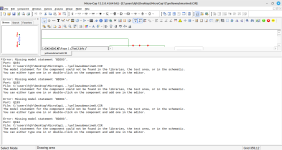
If you open the original attachment in post #333,The CIR is here:
Transient Analysis: Analysis -> Transient -> Run
THD/N: Analysis -> Harmonic Distortion -> Run
When finished, after a minute: From the same window: Harmonic Distortion -> Harmonic Distortion Windows -> chose "Show THD..."
Should look like in the pictures. Does that work for you?
Good morning Bernhard,
there you are again!
changed from 0.003% to an incredible 0.001% at any /witch? point in the THD(a function of ...).
Responsible for this astonishing improvement of this metric is not the type of coupling (we distinguish between dc-coupling, ac-coupling, coupling by means of a base BJT circuit and diode or Z-diode coupling), but the higher gain factor of your throw in the open loop is the cause. Not the Z!
You are comparing apples with oranges and drawing incorrect conclusions. I'm beginning to suspect that this is intentional. Your apodictic assertion tan_delta = D is the same as the memory effect, i.e. the DA of a real capacitor, already spoke volumes.
you want to keep annoying the rest of us boys in our sandbox - again? Please don't do that anymore. Otherwise you can contact me via PM, I have already opened a channel for this. Unfortunately, you have not yet made use of this offer.
All the best,
HBt.
there you are again!
-10dB means:In my schematic, the criticized zdiode vas has about 10dB better THD than the AC coupled VAS from hbt´s latest schematic.
changed from 0.003% to an incredible 0.001% at any /witch? point in the THD(a function of ...).
Responsible for this astonishing improvement of this metric is not the type of coupling (we distinguish between dc-coupling, ac-coupling, coupling by means of a base BJT circuit and diode or Z-diode coupling), but the higher gain factor of your throw in the open loop is the cause. Not the Z!
You are comparing apples with oranges and drawing incorrect conclusions. I'm beginning to suspect that this is intentional. Your apodictic assertion tan_delta = D is the same as the memory effect, i.e. the DA of a real capacitor, already spoke volumes.
That's a bit far-fetched, isn't it?I just resolved that issue, but let´s see if one of our ee overlords has a better solution than the zdiodes.
Is that a threat and does that mean;Enough time till tomorrow evening?
you want to keep annoying the rest of us boys in our sandbox - again? Please don't do that anymore. Otherwise you can contact me via PM, I have already opened a channel for this. Unfortunately, you have not yet made use of this offer.
All the best,
HBt.
- Home
- Amplifiers
- Solid State
- high performance 25W PowerAmp