Yeah for this, BEM simulation is good! expressed it earlier! almost impossible to measure, at least with the home methods.. for example if the passive or active cardioid is good at freespace, is it still good close to wall, or should there be a gap between the speaker? It is just not clear if the cardioid stuff is what we want in the particular thread project, although it looks like one possible solution.It’s also useful to recognise that a cardioid response in the low-frequency region is limited by the fact the speaker is going to be ‘on’ the wall. I haven’t tried this in VituixCAD myself, but using a side porting method like the Dutch&Dutch 8C or the passive cardioid rear ports of the Fulcrum Acoustic stuff might be trickier to verify without a numerical solution.
Analytical and numerical methods all have their place.
AllenB, is this the same thing you refer as the diffraction response near wall? I would agree to find out what it is would benefit the project. Then we could determine if cardioidish was viable on wall system and which implementation of it.
I think if you have active cardioid with side woofers and control each side separately, you have a better chance of steering a null towards the near side wall.
Cardioid mostly helps with lower frequencies. However in this case you have a large baffle (the wall) holding half space. One of the benefits of on wall design is to put the bass on to the wall.
I'm guessing Andy already knows.I would agree to find out what it is would benefit the project.
And my personal project is on wall with cardioid too 😀 but it is not the group project and something else might turn out from the group effort.
Regarding cardioid for low frequencies only, bass coupling to the wall and what not, you are right. It is very easy and natural thing to use tweeter with waveguide on top band and on the bottom we couple to the wall with long enough wavelengths. A cardioid would be helpful between the extremes.
Here is simplest demo on the subject:
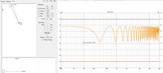
Attached again same made up 30cm distance from wall and only front wall reflection. Ideal driver (omni). As it is seen the first interference null happens somewhere in low mids. The first deep null is there where the path length difference of direct and reflected sound is 1/2 wavelength. Basically, with long enough wavelengths, where the path length difference is roughly < 1/4wl, the direct and reflected sound combine constructively. But, as the frequency rises, wavelength shortens and the interference happens, initially with rather wide nulls that get narrower as frequency rises, a comb filter. The interference pattern is same regardless of the distance to the wall (path length difference), only the frequency / wavelength where the interference starts shifts down as we get longer path length difference.
If we are very close to the wall, so that path length difference goes towards zero, the first null is very high in frequency and we are in half space below that, but this is almost impossible without going inside the wall (or very wide baffle) since almost any drivers have several centimeters worth of structure behind the diaphragm. The shorter we get the path length difference the better in this regard best being flush with the wall, no reflection, no path length difference, no interference.
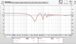
Second attachment is REW psychoacoustic smoothing applied to the first attachment interference pattern. "Psychoacoustic smoothing uses 1/3 octave below 100Hz, 1/6 octave above 1 kHz and varies from 1/3 octave to 1/6 octave between 100 Hz and 1 kHz. It also applies more weighting to peaks by using a cubic mean (cube root of the average of the cubed values) to produce a plot that more closely corresponds to the perceived frequency response." and if we apply that to the interference pattern we see that roughly around 3kHz the "perceived interference" gets to +-1db territory and then vanishes. Worst thing is the lowest dips, very wide null.
Alright, on this ideal scenario there would be few things to do. For the worst interference dips we can push them higher in frequency by reducing path length difference of the front wall reflection and direct sound. Here we had the transducer only 30cm from the wall and few meters listening distance to get path length difference so that first null is as low as 300Hz. On the upper end we have the psychoacoustics to help, as well as waveguide that don't need to be very big to effectively reduce sound to the front wall reflection point as demonstrated in the previous post, above few kiloHertz perhaps. This leaves the bandwidth between roughly 300Hz and up to few kiloHertz that would benefit cardioid response, in this particular example case.
edit. regardless the system being cardioid variety or not, the second attachment shows the main problem bandwidth with front wall reflection with on wall sokutions. The reflected sound combines back with the direct sound which seems to be audible at the mid frequencies unless very thin physicaly. Not considering all the other reflections that happen, sidewall, ceiling and floor, back, which might average things out. Besides using cardioid to attenuate the reflection we could utilize other ways to reduce the interference, for example: rise the reflection zone out from the wall to reduce path length difference, or have attenuation at the first reflection point in form of absorption or active system, very thin panel with beam steering or what have you. But this is the problem, if any, the mid bandwidth that is poisoned by the front wall reflection.
Note, any other speaker system further out in the room would have the same interference problem as well! Only starting lower in frequency as path length through the front wall would be longer. Some attenuation and extra delay with the longer path length might make it less apparent than with the on wall setup we are inspecting here. I don't know. All I want is problem free near wall solution 😉
Regarding cardioid for low frequencies only, bass coupling to the wall and what not, you are right. It is very easy and natural thing to use tweeter with waveguide on top band and on the bottom we couple to the wall with long enough wavelengths. A cardioid would be helpful between the extremes.
Here is simplest demo on the subject:
Attached again same made up 30cm distance from wall and only front wall reflection. Ideal driver (omni). As it is seen the first interference null happens somewhere in low mids. The first deep null is there where the path length difference of direct and reflected sound is 1/2 wavelength. Basically, with long enough wavelengths, where the path length difference is roughly < 1/4wl, the direct and reflected sound combine constructively. But, as the frequency rises, wavelength shortens and the interference happens, initially with rather wide nulls that get narrower as frequency rises, a comb filter. The interference pattern is same regardless of the distance to the wall (path length difference), only the frequency / wavelength where the interference starts shifts down as we get longer path length difference.
If we are very close to the wall, so that path length difference goes towards zero, the first null is very high in frequency and we are in half space below that, but this is almost impossible without going inside the wall (or very wide baffle) since almost any drivers have several centimeters worth of structure behind the diaphragm. The shorter we get the path length difference the better in this regard best being flush with the wall, no reflection, no path length difference, no interference.
Second attachment is REW psychoacoustic smoothing applied to the first attachment interference pattern. "Psychoacoustic smoothing uses 1/3 octave below 100Hz, 1/6 octave above 1 kHz and varies from 1/3 octave to 1/6 octave between 100 Hz and 1 kHz. It also applies more weighting to peaks by using a cubic mean (cube root of the average of the cubed values) to produce a plot that more closely corresponds to the perceived frequency response." and if we apply that to the interference pattern we see that roughly around 3kHz the "perceived interference" gets to +-1db territory and then vanishes. Worst thing is the lowest dips, very wide null.
Alright, on this ideal scenario there would be few things to do. For the worst interference dips we can push them higher in frequency by reducing path length difference of the front wall reflection and direct sound. Here we had the transducer only 30cm from the wall and few meters listening distance to get path length difference so that first null is as low as 300Hz. On the upper end we have the psychoacoustics to help, as well as waveguide that don't need to be very big to effectively reduce sound to the front wall reflection point as demonstrated in the previous post, above few kiloHertz perhaps. This leaves the bandwidth between roughly 300Hz and up to few kiloHertz that would benefit cardioid response, in this particular example case.
edit. regardless the system being cardioid variety or not, the second attachment shows the main problem bandwidth with front wall reflection with on wall sokutions. The reflected sound combines back with the direct sound which seems to be audible at the mid frequencies unless very thin physicaly. Not considering all the other reflections that happen, sidewall, ceiling and floor, back, which might average things out. Besides using cardioid to attenuate the reflection we could utilize other ways to reduce the interference, for example: rise the reflection zone out from the wall to reduce path length difference, or have attenuation at the first reflection point in form of absorption or active system, very thin panel with beam steering or what have you. But this is the problem, if any, the mid bandwidth that is poisoned by the front wall reflection.
Note, any other speaker system further out in the room would have the same interference problem as well! Only starting lower in frequency as path length through the front wall would be longer. Some attenuation and extra delay with the longer path length might make it less apparent than with the on wall setup we are inspecting here. I don't know. All I want is problem free near wall solution 😉
Attachments
Last edited:
Here is few more of the simplest kind.
I mentioned in the last post that as the path length difference gets longer the interference pattern just comes down in frequency. Here is few to this.
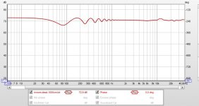
First attachment, everyone says that speakers sound better as they are farther from walls. If it was only for the frequency response / interference here is why, psychoacoustic smoothing applied ideal point source 1m from front wall (2m path length difference). Just to demonstrate how these look on the graphs. Note how the pattern of the interference is same as previous post, just lower in frequency. Comparing the 1m away or on wall, the main difference would be the smoothed ripple gets within +-1db below 1kHz when positioned further out! Not considering time difference and other possible phenomena, but this alone would suggest further out sounds better.
Now, what if the driver beams? Surely there will be frequency above which not much interference happens because of the beaming, no much sound to the back? Two GIFs demonstrate this, the first one is ideal 8" driver on minimal 21cm x 21cm baffle, and the second one is ideal ~3" driver on minimal 11cm x 11cm baffle. This is very interesting to tweak realtime in vituixCAD as the interference just pulls out from the DI ~10db region as the driver is pulled out from the wall 😀 Anyway, only centimeter or two out there is huge interference and smack dap at the most sensitive region for ear, around and above 1kHz. The smaller driver just has the same phenomenon higher up in frequency. If I did this with 15" driver, it would be quite similar, 10db DI point is just about 1kHz when with the 8" it is around 2kHz and with the 3" around 5kHz.
This is easy test to setup, few clicks and anyone can try and reason what the implications might be 🙂 Toe in and listening triangle doesn't change the situation much to the straight on used in the example, it is the path length difference that matters. Even if we didn't know how much this all affects to sound, this is still what the difference is between on-wall and furhter out position, the interference is higher up in frequency.
edit.
This "knowledge" can be exploited with a cardioid speaker system. If one makes 8" cardioid mid like the D&D 8c, there is certain bandwidth where the cardioid response is due to size of the construct. Now, just pull out the speaker just right distance from the wall to have the interference happen within the cardioid bandwidth! Basically, the driver size determines the upper end of the bandwidth, where the crossover would be, and then it can be pulled out from the wall as much but no further as the interference still falls into the passband. My 8" can be crossed between 1-2kHz (got smaller and bigger waveguide) and the woofer seems to be fine crossed around 200Hz but max SPL would increase if crossed higher. This means the driver (speaker) can be brought maybe 20cm out from the wall, about the diameter of the driver. This seems to apply for 3" driver example as well. It could have cardioid response to cover from ~3-4kHz to maybe 500Hz with max distance from the wall of 10cm.
While we get nicer smaller system with smaller drivers it will limit the max SPL in this particular application (3 way on wall with cardioid mid). Because having to cross to a woofer below the 200Hz or 500Hz requires the woofer to have the same small distance to couple with the wall so that we don't have to use cardioid there no more! Which in turn limits the SPL capability of the system because it limits the size of the bass. Or makes a 4 way system.
Anyway, some food for thought for you all.
I mentioned in the last post that as the path length difference gets longer the interference pattern just comes down in frequency. Here is few to this.
First attachment, everyone says that speakers sound better as they are farther from walls. If it was only for the frequency response / interference here is why, psychoacoustic smoothing applied ideal point source 1m from front wall (2m path length difference). Just to demonstrate how these look on the graphs. Note how the pattern of the interference is same as previous post, just lower in frequency. Comparing the 1m away or on wall, the main difference would be the smoothed ripple gets within +-1db below 1kHz when positioned further out! Not considering time difference and other possible phenomena, but this alone would suggest further out sounds better.
Now, what if the driver beams? Surely there will be frequency above which not much interference happens because of the beaming, no much sound to the back? Two GIFs demonstrate this, the first one is ideal 8" driver on minimal 21cm x 21cm baffle, and the second one is ideal ~3" driver on minimal 11cm x 11cm baffle. This is very interesting to tweak realtime in vituixCAD as the interference just pulls out from the DI ~10db region as the driver is pulled out from the wall 😀 Anyway, only centimeter or two out there is huge interference and smack dap at the most sensitive region for ear, around and above 1kHz. The smaller driver just has the same phenomenon higher up in frequency. If I did this with 15" driver, it would be quite similar, 10db DI point is just about 1kHz when with the 8" it is around 2kHz and with the 3" around 5kHz.
This is easy test to setup, few clicks and anyone can try and reason what the implications might be 🙂 Toe in and listening triangle doesn't change the situation much to the straight on used in the example, it is the path length difference that matters. Even if we didn't know how much this all affects to sound, this is still what the difference is between on-wall and furhter out position, the interference is higher up in frequency.
edit.
This "knowledge" can be exploited with a cardioid speaker system. If one makes 8" cardioid mid like the D&D 8c, there is certain bandwidth where the cardioid response is due to size of the construct. Now, just pull out the speaker just right distance from the wall to have the interference happen within the cardioid bandwidth! Basically, the driver size determines the upper end of the bandwidth, where the crossover would be, and then it can be pulled out from the wall as much but no further as the interference still falls into the passband. My 8" can be crossed between 1-2kHz (got smaller and bigger waveguide) and the woofer seems to be fine crossed around 200Hz but max SPL would increase if crossed higher. This means the driver (speaker) can be brought maybe 20cm out from the wall, about the diameter of the driver. This seems to apply for 3" driver example as well. It could have cardioid response to cover from ~3-4kHz to maybe 500Hz with max distance from the wall of 10cm.
While we get nicer smaller system with smaller drivers it will limit the max SPL in this particular application (3 way on wall with cardioid mid). Because having to cross to a woofer below the 200Hz or 500Hz requires the woofer to have the same small distance to couple with the wall so that we don't have to use cardioid there no more! Which in turn limits the SPL capability of the system because it limits the size of the bass. Or makes a 4 way system.
Anyway, some food for thought for you all.
Attachments

Last edited:
This illustrates problem with the simplified version. When you only consider one boundary the result will not be at all valid higher in frequency, in practice.Second attachment is REW psychoacoustic smoothing applied to the first attachment interference pattern. and if we apply that to the interference pattern we see that roughly around 3kHz the "perceived interference" gets to +-1db territory and then vanishes. Worst thing is the lowest dips, very wide null.
In a room, by about 1KHz the speaker is in control and the interference has reduced to very little. All of the sources real and reflected/diffracted are combining together and settle down to a predictable response. You can see this in Vituix too, that when more sources are added the interference goes down.
As you add in more boundaries the peak dip pattern changes and it depends on distance too, how much absorption the surface has etc. This is difficult to make generic.
Toeing in is a big question too. On wall placement makes that tricky if the speaker is going to be thin, or have the baffle angled like in Markus's drawings linked earlier. Adjusting it after will be hard, and it will have an impact on the distances to the wall on either side.
As all speakers will suffer the boundary interference from surfaces other than the front wall in a similar way, it would make sense to me to begin with optimizing a shape in an infinite baffle simulation so that the speaker deals with that surface alone as well as it can, the hemi anechoic response.
Do you see how the listening distance moves with the position of the speaker? The distance in Vituix is from the front baffle, it might not make a huge difference but you might want to consider it when making comparisons.Two GIFs demonstrate this
Yes I know, the listening distance stays the same in VCAD. How ever this is not relevant for the demonstration since we have the path length difference that makes the interference happen and determines the frequencies the nulls are. Moreover everyone's listening situation varies. Only thing we can deduct from this is that the path length difference of direct and reflected sound can be minimized bringing the speaker closer to wall and maximized taking it further out. It is pretty bad between path length difference of 1cm - 100cm. Then there are some cheats we can apply like bring just the reflection point closer, apply some attenuation to the reflection one way or another. Attenuation is very best option to my logic, to the frequency range that has the sparse interference dips = 1/4 wl and up.
As what comes to the multiple boundaries all making reflection and contribute to the frequency response at listening position, yes definitely. And VCAD doesn't even have only but the one room corner to test with. It might turn out that there is so much going on in the rooms so that the interference doesn't matter much if it all averages out. Although, people seem to report close wall sounds poo and further out sounds best, it would indicate there is something to it. And wasn't it Toole who had to make a revision of the book to correct the early reflection point of view?😀 Be it time delay difference or something else, or just the interference from the front wall being worse sounding somehow, that is visible in the simple experiments here.
Anyway, I've made many experiments with the simple VCAD room model and it looks like there is nothing I can do to average out the 1kHz region with speaker and driver positioning and radiation patterns. Low mids seem to even out with speaker positioning and then some with cardioid pattern but the 1kHz shows anomalies no matter what 😀 basically a very narrow pattern waveguide there, or MTM configuration helps, brute force attenuation towards the ceiling and floor reflections. None of this might not matter though, I don't know how audible it is and how it affects. Just an observation from experiments.
Last edited:
Do you mean interference goes up but the effect seen in the frequency response to particular direction goes down because things average out? 🙂Frequency of "beaming", or control, depends of the physical size of direct radiating stuff, or from the waveguide if there is one. Wide panel has less sound to the back but how much to the sides depends on the driver (if wavelength is long enough so that the self interference doesn't make it beam yet). Attached is the 3" ideal driver on 11cm baffle with sixpack showing. At some path length difference there is interference all the way up to 5kHz! 8" had it to 2kHz. We could use wider baffle to have more control , but then the toe in goes impossible and there would still be sound towards the wall (thinking Markus's drawings). But, it could be so that the wall reflects somewhere else than to the listening spot! It would be paramount to make the baffle / wall integration seamless though, to not have diffraction appear which would pretty much equal a reflection I think.This illustrates problem with the simplified version. When you only consider one boundary the result will not be at all valid higher in frequency, in practice.
In a room, by about 1KHz the speaker is in control and the interference has reduced to very little. All of the sources real and reflected/diffracted are combining together and settle down to a predictable response. You can see this in Vituix too, that when more sources are added the interference goes down.
edit.
My demos are a bit misleading, since AllenB noted earlier the reflection line to the wall in the room view goes through the box. Yes it does, I'm trying to demonstrate the path length difference and not how it looks on the room view, only the graphs matter. We are dealing with reflection from wall, which we could possibly get rid of or at least attenuate. I've got the 3D model on the forehead🙂
Very, but I've tried to construct the demonstrations on few previous posts this in mind. With practical sized boxes, drivers, that could fit the project description there seems to be not much slack how they can be arranged. Too far out from the wall and the bass doesn't couple, so better stick as close as possible and attenuate radiation to the reflection as much as possible above that. Thats about the best we can do I think, at least for the systems I've been able to think through 😀 With constant directivity, and possibility for low diffraction and toe in. It looks like the nominal 90 deg pattern is enough to reduce the interference nicely.As you add in more boundaries the peak dip pattern changes and it depends on distance too, how much absorption the surface has etc. This is difficult to make generic.
We could utilize the more sources, more interference somehow. Perhaps using some array, or panel, very flat against the wall. Maybe steer the sound if there is need.
Wide stuff is hard to toe in. If staying as wide as deep, the thing can rotate without taking more space.Toeing in is a big question too. On wall placement makes that tricky if the speaker is going to be thin, or have the baffle angled like in Markus's drawings linked earlier. Adjusting it after will be hard, and it will have an impact on the distances to the wall on either side.
As all speakers will suffer the boundary interference from surfaces other than the front wall in a similar way, it would make sense to me to begin with optimizing a shape in an infinite baffle simulation so that the speaker deals with that surface alone as well as it can, the hemi anechoic response.
How about horizontal line array from wall to wall with programmable sections to steer the sound where ever? 😀 send sound to middle for movies, widen for stereo. steering and cancellation possible. Maybe to ceiling corner for it to be out of sight and have less issues with floor / ceiling bounce than somewhere at listening height, which would be occupied by TV anyway.
Everyone, let your imagination fly!😀
Attachments

Last edited:
In a good world, we would have more ambience from the venue in the recording and less from the room we reproduce in - then wall placement would be the best one could do - only surpassed by corner. A semi solution is speakers in the side walls. Wall + added ambiance is an other one?
//
//
In a steady state curve it will average out but that doesn't mean that it doesn't matter. When and where you hear reflected sound from matters a lot.It might turn out that there is so much going on in the rooms so that the interference doesn't matter much if it all averages out.
"People" report many things. A speaker designed to be used away from boundaries will not sound great if moved closer to a boundary and left unequalised. I use my own speakers with the front baffle 500mm away from the front wall at the furthest edge. This isn't an accident it was determined this position gave the smoothest overall response with the least un-correctable nulls.Although, people seem to report close wall sounds poo and further out sounds best, it would indicate there is something to it.
Smiley face notwithstanding, the clarification of position was necessary due to "people" misinterpreting his writing when not reading the whole book and considering it within context. There is no right and wrong with early reflections, they can be helpful and harmful and personal preference in music and what you seek out of that music will determine which side of the fence you land on.And wasn't it Toole who had to make a revision of the book to correct the early reflection point of view?😀
Think of it as a limited reflection model, rather than a room model. The fact that your simulations don't match measured reality should be a clue that the simulation is limited in some way.Anyway, I've made many experiments with the simple VCAD room model and it looks like there is nothing I can do to average out the 1kHz region with speaker and driver positioning and radiation patterns. Low mids seem to even out with speaker positioning and then some with cardioid pattern but the 1kHz shows anomalies no matter what.
The more separate sources you add the more the peak and dip combinations average out to a smoother response. The same thing happens in reality as the density of the modes in a room increases the effect of the reflections settles down. The more separated the modes become the more obvious their effect is.Do you mean interference goes up but the effect seen in the frequency response to particular direction goes down because things average out? 🙂Frequency of "beaming", or control, depends of the physical size of direct radiating stuff, or from the waveguide if there is one.
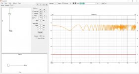
Only had a short time free yesterday but made some progress. The weird plot shown earlier was due to user error/misunderstanding rather than software bugs. This became apparent when I got the BEM++ software working to some extent and saw pretty much the same thing with my test case. Current plot using acousto attached.
Both BEM solvers have issues which make them less than ideal for our purposes. Both need a modest amount of scripting to manipulate the input grid and field data from the upstream grid generation stage and to manipulate it for the downstream evaluation and plotting stage. This is not a significant issue just part of adapting research-type software to our needs. Nonetheless they both seem to work if not as well I would like. Rather than continue looking at BEM solvers (I have noticed one or two that might be possibilities) I am going to pick one of the current two and adapt it to use for the initial on wall study. Not sure which one yet.
Perhaps I should add that I am keeping in mind what we will need later in the project when designing the details of the cabinet structure and simulating the radiation from the vibrating cabinet rather than just the driver. I have used acousto for this before a few years ago but it was a bit fiddly in terms of input files.
Last edited:
What this clean 105+ dB peaks at listening position could be at one meter and what means clean?
What could be box dimensios? I assume this is going to be flat box.
I have some difficulties to understand talk about cardioid radiation in case of on wall speaker. I think front wall reflections are no problem, because speaker is practically front wall.
What could be box dimensios? I assume this is going to be flat box.
I have some difficulties to understand talk about cardioid radiation in case of on wall speaker. I think front wall reflections are no problem, because speaker is practically front wall.
^ Andy, can't we reason that from simple model pretty nicely, and make some rough estimates what is needed to reduce effect of front wall?
Yes. Or you could simply go with what you feel good about. It is a hobby so employ the approach to design that maximises your fun/satisfaction.
Competent 3D simulations provide information to make better quality design decisions particularly about details. Nothing more. The cost in time and effort is significant and so high quality design decisions have to be important and valued. It is the dominant approach used in the high-to-medium tech engineering industry but less so a low-tech engineering industry like home audio speakers but it is growing.
What this clean 105+ dB peaks at listening position could be at one meter and what means clean?
High fidelity at standard listening levels requires that the direct sound at the listening position is not significantly distorted. At 1m the minimum requirement would be more like 115+ dB clean peaks with perhaps another 10 dB or so to do loud cleanly.
What could be box dimensios? I assume this is going to be flat box.
It is one of three approaches being considered. The dimensions will be determined by the requirements for high fidelity on a wall.
I have some difficulties to understand talk about cardioid radiation in case of on wall speaker. I think front wall reflections are no problem, because speaker is practically front wall.
One of the ideas I would like to explore within this project is to largely replace decisions based on think/feel with ones justified by fully quantified values. The 105+ dB is an example of this although the few sentences discussing the assumptions it is based on have yet to be written down in the introduction/background for the project.
We also haven't setup a repository yet in which the introduction/background would be stored. Github is an option. Is this a good choice or are others better?
If nobody sets up a repository earlier I will do it in a few days time in order to present the initial set of simulations for people to look at, check and tweak.
"One of the ideas I would like to explore within this project is to largely replace decisions based on think/feel with ones justified by fully quantified values."
Horray!! 👍
//
Horray!! 👍
//
Wide and shallow is probably the way to go. I dont see the idea with sidefiring woofers, since its not supposed to play bass.
Cheers!
Cheers!
- Home
- Loudspeakers
- Multi-Way
- High Fidelity On Wall Speaker Group Project