Does the scope have an isolated ground for one or more inputs? I've never seen that on a mains powered scope.
It has a common ground.
With the digital scope to measure correctly the oscilloscope wants/needs a groundconnection to the source, to measure correctly in the base set up for pseudo differential measuring.
Up and down with the 12V source and no jump with both leads connected to +.
I measured the high side again, with the probes switched.
i noticed that the probe didn´t make good contact in the channel 1 connector (didn´t switch to 10:1 setting auto)
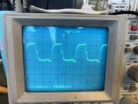
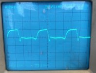
The First Pic is the low side
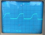
The second pic is the high side now
With the digital scope to measure correctly the oscilloscope wants/needs a groundconnection to the source, to measure correctly in the base set up for pseudo differential measuring.
Up and down with the 12V source and no jump with both leads connected to +.
I measured the high side again, with the probes switched.
i noticed that the probe didn´t make good contact in the channel 1 connector (didn´t switch to 10:1 setting auto)
The First Pic is the low side
The second pic is the high side now
Attachments
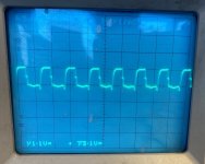
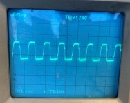
The low-side is correct. The high-side shouldn't be going below the reference. The waveform in post #35 is mostly right but the falling side of the waveform should fall farther before the notch.
Are the FETs you're using the factory original part number?
Are the 21844 ICs from a reputable distributor?
Are the FETs you're using the factory original part number?
Are the 21844 ICs from a reputable distributor?
21844 are from mouser, the FET´s are the FDA59N30 also from mouser, ONSemi bought fairchild but that shouldn´t make a difference.
What could cause the driver to give out that signal, the outputs should be symmetrical in amplitude?
The poor high-side signal could be due to a bad driver or the wrong FETs but Mouser is a reliable distributor.
Are the gate resistors within tolerance?
Post #46: Was this at the output of the driver IC or was it at the output transistor?
Are the gate resistors within tolerance?
Post #46: Was this at the output of the driver IC or was it at the output transistor?
Post #46 was measured directly at the driver outputs.
The R-Gate are all at 33R1 or 33R2 or 33R4
The R-Gate are all at 33R1 or 33R2 or 33R4
Not in the traditional sense of the word.
Looking at all of the waveforms and cherry picking them, I think the deadtime may be the problem. Before I'd make any modifications, I'd suggest installing all of the outputs for one driver IC and comparing the heating to the other two (incomplete) banks of FETs.
Looking at all of the waveforms and cherry picking them, I think the deadtime may be the problem. Before I'd make any modifications, I'd suggest installing all of the outputs for one driver IC and comparing the heating to the other two (incomplete) banks of FETs.
The feedback loop meets for both sides at the same 1,8Mohm resistor before being fed into the OpAmps.
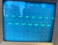
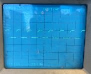
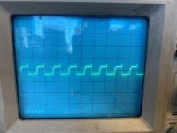
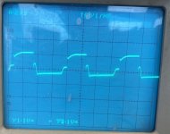
With ultra fast diodes over the gate resistors the GS-waveform look like this.
This reduces the turn off spike, and the turn off flank.
The fets get less hot.
I will try to compare the heat behaviour between the 2 „channels“ next week and how it changes the waveform when all fets are built in.
With ultra fast diodes over the gate resistors the GS-waveform look like this.
This reduces the turn off spike, and the turn off flank.
The fets get less hot.
I will try to compare the heat behaviour between the 2 „channels“ next week and how it changes the waveform when all fets are built in.
Attachments


With all of the FETs and diodes in one half, compare the driver IC temperature to the half with no diodes. With no series resistor (with the diode), the driver IC may run hot.
Drive
Attachments
-
 26473F11-5ED0-4D35-B8D3-4B8517CD6CC4.jpeg365.6 KB · Views: 47
 -
 C1B5662D-1545-4AD8-99B2-A97CB26C04E7.jpeg379.6 KB · Views: 48
 -
 052763C6-2790-4859-AB64-6766AE32B8AE.jpeg315.1 KB · Views: 55
 -
 9E5E8D7B-5EE7-4F0C-8963-4647B585991D.jpeg328.4 KB · Views: 48
 -
 13F007D7-1727-41F5-972C-2846D8E9ABE7.jpeg373.2 KB · Views: 43
 -
 98963A7C-E013-485A-A531-A707B36200F2.jpeg370.3 KB · Views: 47
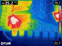
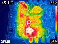
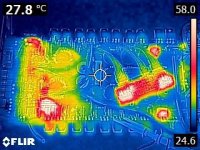
with diodes the driver get´s less hot, but still both get to hot to touch.
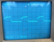
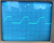
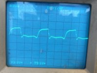
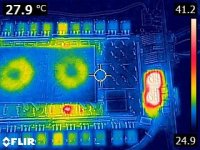
Picture 3 is High Side directly at the driver and Picture 5 is low-side.
The output fet´s don´t get hot, but the bottom left side fet is getting hotter than the others.
I desoldered the Turn On and Turn Off resistors, they all show 33R2 and 99,8kOhm at this row.
Picture 3 is High Side directly at the driver and Picture 5 is low-side.
The output fet´s don´t get hot, but the bottom left side fet is getting hotter than the others.
I desoldered the Turn On and Turn Off resistors, they all show 33R2 and 99,8kOhm at this row.
Attachments
-
 FLIR0217.jpg34 KB · Views: 54
 -
 FLIR0216.jpg74.1 KB · Views: 50
 -
 FLIR0215.jpg32.2 KB · Views: 56
 -
 FLIR0214.jpg79.4 KB · Views: 52
 -
 FLIR0213.jpg33.6 KB · Views: 52
 -
 FLIR0212.jpg97.7 KB · Views: 55
 -
 FLIR0211.jpg35.9 KB · Views: 60
 -
 FLIR0210.jpg83.2 KB · Views: 59
 -
 FLIR0209.jpg36.1 KB · Views: 47
 -
 FLIR0218.jpg99.6 KB · Views: 49
If only one FET is heating more than others, swap its position with one that's in parallel with it to see if the heating follows the transistor.
I will do that.
cherry picking my last scope-photos again does it seems better that way with the dead time?
cherry picking my last scope-photos again does it seems better that way with the dead time?
The fact that the outputs are running cool means things are OK. The drive signals look better. It's hard to believe that the driver driving the FETs with diodes is running cooler. The lack of a resistor between the gate and the drive is tough on a driver.
The board has holes for a heatsink. If you don't have a heatsink, you might want to make a heatsink from a piece of aluminum or copper stock to install on the driver ICs.
The board has holes for a heatsink. If you don't have a heatsink, you might want to make a heatsink from a piece of aluminum or copper stock to install on the driver ICs.
- Home
- General Interest
- Car Audio
- Hifonics BXi 8000D - good waveforms?