Thank for tip, that was half right.
I did resoldering, d2 was indeed one side soldered. Resoldered rest of diodes and still 135-140v AC on vneg-vpos. I've found no AC on vneg-0 and vpos-0.
Can you post a picture of your test setup.
Hi Bonsai,
Thanks for the info. I've made a LT Spice schematic and checked various possibilities/permutations.
Unless Q5 is 'in circuit' then the dissipation of R19 is going to be around 20W.
My 'NJWs' output transistors are stuck in transit because of COVID-19 so I'm experimenting with the 2SA1295/2SC3264 combination (which I have).
I was just trying to check if the amp was working correctly before adding the 2SA/2SC's
I'll send a pic of the test setup a little later when I've connected the power transistors.
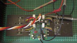
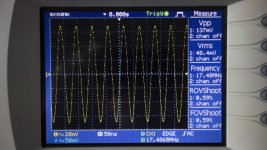
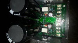
Here's one channel of my xK amplifier. Mounted on my test heatsink (0.4°C/W) and attached the 2SA/2SC output transistors. Power is from a Ripple Eater @ ± 32.5V per channel.
All measured voltages pretty much in line with the specs other than R10/R11 at ± 655 mV (vs 400 - 500 mV spec)
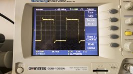
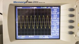
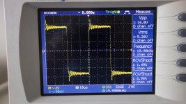
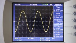
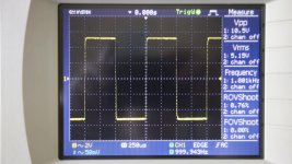
Square wave at 1V RMS shows some over and undershoot. Not sure if this is a problem?
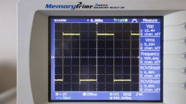
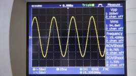
Without an input signal (input shorted to earth) there's also a signal appearing at 16.5 MHz which I need to try and find out where it comes from.
Otherwise as per attached pictures.
Comments?
All measured voltages pretty much in line with the specs other than R10/R11 at ± 655 mV (vs 400 - 500 mV spec)
Square wave at 1V RMS shows some over and undershoot. Not sure if this is a problem?
Without an input signal (input shorted to earth) there's also a signal appearing at 16.5 MHz which I need to try and find out where it comes from.
Otherwise as per attached pictures.
Comments?
Attachments
Hmm. You should not have that oscillation there. I’ll take a look at the output device specs - looks like that’s where there may be an issue. The 16MHz oscillation is a bit too high for it to be a feedback loop related issue. Looks more like an output stage parasitic oscillation problem.
Can you send a close-up pic of the two compensation caps you are using - if those were too low in value, you would have the problems you see with the overshoot. This looks like a loop compensation problem.
Can you send a close-up pic of the two compensation caps you are using - if those were too low in value, you would have the problems you see with the overshoot. This looks like a loop compensation problem.
Hi Bonsai,
All the transistors were 'as specified' KSA1381/KSC3503, KSC2690A/KSA1220A (ex Digikey) except for BC550/560 and the 2SC3264/2SA1295 (ex Farnell about 6 years back).
150 pF caps (C2, C3, C10) were from Digikey (FKP2C001501D00JSSD) - are these the ones your interested in?
Input cap (C4) was ECEA1HN220U Panasonic 22uF 50V
C15 was a 270 pF Silver Mica (only one I could find with the right capacitance and pin spacing) ex RS.
I'll try send a better picture of the board tomorrow when it's light.
Just let me know if there's anything else you need
Tony,
I hope you get your NJW output transistors soon! Judging by the output wiring to your 2SC/2SA transistors, I have an eery feeling that output oscillation is the crux of your issue.
Best,
Anand.
I hope you get your NJW output transistors soon! Judging by the output wiring to your 2SC/2SA transistors, I have an eery feeling that output oscillation is the crux of your issue.
Best,
Anand.
Hi Anand,
The MT-200 package unfortunately is too large to directly solder to the PC board (they overlap) so I made temporary connections to the 'trial' heat sink that I have used previously - which is why it looks a bit like Swiss cheese.
The holes for the NJW are already drilled and tapped. Placed the order on the Monday and we went into 'lock down' on the Friday - so I just missed out by a day or 2 getting them :-(
Hi again.
Thanks for patience. 'Ima special case...
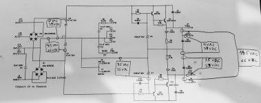
Here's measurements of ripple eater.
I desoldered c5 and c7 and checked theyr'e fine.
Measurement on image is done with inverted probes polarity, when I set to proper probe polarity measurements are the same, but on second half of RE.
Thanks for patience. 'Ima special case...
Here's measurements of ripple eater.
I desoldered c5 and c7 and checked theyr'e fine.
Measurement on image is done with inverted probes polarity, when I set to proper probe polarity measurements are the same, but on second half of RE.
Attachments
Hi again.
Thanks for patience. 'Ima special case...
Here's measurements of ripple eater.
I desoldered c5 and c7 and checked theyr'e fine.
Measurement on image is done with inverted probes polarity, when I set to proper probe polarity measurements are the same, but on second half of RE.
You shouldn't have any AC on the output of your bridge rectifier D4 - only DC.
Therefore AFAIK:
- The bridge rectifier is the wrong type (i.e. with different pinouts)
- The Bridge rectifier is inserted the wrong way round.
- The Bridge is 'blown' or otherwise faulty
- You have 'bridged' solder joints allowing AC through
So finally the NJW trannies arrived. Installed 'on-board' to the second Amp board and fed with ±32V and input shorted the voltage 'check point's were all in spec other than R10/R11 voltages @ 566/577 mV (450 ±50 mV spec) due, presumably, to the higher supply line voltages.
The amp board was connected to a ripple eater and the zobel network connected - but no 8 Ohm output resistor.
Unfortunately the ±17 MHz spurious wave still persists as per the 2SA/2SC transistors (connected 'off-board') as previously reported. (Picture)
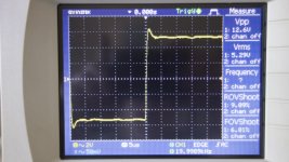
Applying a 250 mV RMS 20 kHz square wave results in severe ringing'/oscillation. (Picture)
Adding a 50W 8.2 Ohm 'dummy load' to the output blows the power supply fuses (5A) - both when the load is attached 'live' or when it's already attached at 'power-up'.
In the first instance (input shorted) touching the '0V' side of either the R36/R37 resistors with a DVM probe 'collapses' the 17 mHz spurious waveform.
This ± 17 mHz signal is detected at the bases of Q10/Q11 and the NJW bases but not on Q3/Q4 bases.
In the second instance, (20kHz Sq Wave) touching R36/R37 with the DVM probe makes no difference as to the ringing on the wave (that I can see). Didn't check up at 17 mHz.
BTW Connecting or disconnecting the Zobel network doesn't seem to affect the 17 MHz wave.
The spurious oscillation varies from around 16.2 to 17.5 MHz or so. Rarely seems to be the same twice.
Meanwhile the BD139 (Q2) on the ripple eater has now blown for a second time (first time was on the 2SA/2SC board). Perhaps when I disconnected the Zobel with live power, not sure.
The amp board was connected to a ripple eater and the zobel network connected - but no 8 Ohm output resistor.
Unfortunately the ±17 MHz spurious wave still persists as per the 2SA/2SC transistors (connected 'off-board') as previously reported. (Picture)
Applying a 250 mV RMS 20 kHz square wave results in severe ringing'/oscillation. (Picture)
Adding a 50W 8.2 Ohm 'dummy load' to the output blows the power supply fuses (5A) - both when the load is attached 'live' or when it's already attached at 'power-up'.
In the first instance (input shorted) touching the '0V' side of either the R36/R37 resistors with a DVM probe 'collapses' the 17 mHz spurious waveform.
This ± 17 mHz signal is detected at the bases of Q10/Q11 and the NJW bases but not on Q3/Q4 bases.
In the second instance, (20kHz Sq Wave) touching R36/R37 with the DVM probe makes no difference as to the ringing on the wave (that I can see). Didn't check up at 17 mHz.
BTW Connecting or disconnecting the Zobel network doesn't seem to affect the 17 MHz wave.
The spurious oscillation varies from around 16.2 to 17.5 MHz or so. Rarely seems to be the same twice.
Meanwhile the BD139 (Q2) on the ripple eater has now blown for a second time (first time was on the 2SA/2SC board). Perhaps when I disconnected the Zobel with live power, not sure.
Attachments
Tony,
Apologies for the delayed response. Clearly there is some serious issue here.
I am tied up today but will come back to you later to try to help you sort it out.
As a first step, can you short out the bias generator Q7 collector to emitter and then drive the amp. You will have very bad cross-over distortion, but I want to make sure it’s not opening up for some reason and causing high currents to flow. While testing and setting up the amp, do not use the ripple eater. Only connect that in circuit one everything is running ok To do this, short out the ripple eater pass transistors.
Please recheck the values for C2, C3, C10 and R42 - if these compensation values are not correct, they will lead to problems.
Last edited:
Thanks for the reply Bonsai.
I had thought using the NJW power trannies on the second board would sort it out but unfortunately it's worse :-(
Anyway, I can run the amp directly from the first bank of caps I used prior to the RE. Obviously not that well regulated (2 banks of 3 by 5,600 uF) but should suffice.
I have double checked all components (and had actually physically measured each one prior to insertion on both boards) but I'll check again.
Bias generator:
First time with SMD components. Hope I haven't fried them during soldering so I'll try and check those too. Q7 is a BC550. Was purchased locally as 'OnSemi' but looking at them I wasn't convinced they were 'genuine'.
Ripple Eater:
I've removed the ripple eater and replaced the BD140 (-16). The collector/Base was fried (shorted).
Anyway, even disconnected I can use it for the ZN we spoke about previously and place it much closer to the amp board than previously.
Will recheck C2, C3, C10 and R42 too
Will keep you informed.
Cheers
Can you check that D1 is installed the right way and is ok as well.
Strange that you are popping fuses - that seems to indicate either gross Very HF oscillation leading to cross conduction or that the bias generator is opening up for some reason - just thoughts off the top of my head.
If C16 was short, this would also cause a problem, but unlikely for this to be on two boards.
Hi Bonsai
A few points that have arisen:
C2/C3/C10 are Wima 150/63 150pF caps recently purchased from US. Small query that the pins are not parallel to the sides (they mount slightly 'skew'). Not what I expect from Wima.
R42 is indeed 1k8
D1 is installed 'as per the PCB silk screen orientation and a quick check insitu shows it's working.
Can't measure C16 installed on PCB but resistance shows as ±32K so it's not shorted.
Some measurements using the Digimess power supply. Voltage doesn't set accurately and can vary (maybe the pot) but it does also have amps out which seems to work OK.
No ZN or 8R dummy load attached.
Circuit board with NJW's 'as is'
Input shorted, ±22V supply and output adjusted to <5mV
Current draw 500 mA. Spurious signal @ 15.3 mHz and 94 mV RMS output as per picture
Input signals at 250mV RMS:
Current Draw of 520 mA @ ±23V
Definite signs of instability on 1 and 20 kHz square waves but signs of over/undershoot
Sine waves at 1 & 20 kHz look 'noisy'.
Check on (Bias) jumper pins 1 & 2 (as per schematic)
No signal applied, ±25V supply:
Pin #1 -1.34V (DVM), Scope: 'No signal'
Pin #2 -219 mV (DVM), Scope: 2 mV, 16 mHz noisy sine wave
250 mV Signal applied:
Pin #1 (connected to 1n4148 anode)
1 and 20kHz sine signals look 'OK' (Picture)
1 and 20 kHz square waves look OK 'Wave shape' (HF roll off), no signs of over or undershoot.
Pin #2 (connected to Q7 emitter)
1 kHz sine looks 'ok' but square wave ('normal shape' - i.e. rectangular) has overshoot
20 Khz sine wave looks 'OK', if somewhat 'noisy', square wave noisy with overshoot.
As requested:
Q3/Q4 collectors joined (i.e. Q7 C/E shorted out):
Input shorted
Current draw 20 mA (!) at ± 19.5V. No spurious signal at ± 17 mHz
250 mV signals applied:
Current Draw 30 mA at ± 23V
Sine 1 kHZ looks 'OK', Square wave has overshoot (Pictures)
Sine at 20 kHz looks 'Wobbly' as does the square wave plus overshoot (Picture)
NB: No signs of cross over distortion
I'll keep on seeing what I can find but looks like the bias circuit has a problem?
Should have taken some more pics but swapping wires, changing settings I forgot to take some
Attachments
The low supply current with bias transistor Q7 shorted collector to emitter is correct. Can you check Q7 carefully - make sure it is the correct type and not inadvertently a PNP. Can you measure the voltage across the devices base - emitter junction. It should be about 0.6V
Hello all. Just ordered parts and PCB’s and looking forward to building and listening to what seems, like an excellent amp.
I’m planning out a non-conventional heatsink arrangement (i.e. not a typical chassis) and was wondering what the dimensions of the amp PCB’s are. Does anyone know the overall size of the boards?
Thanks
Bob
I’m planning out a non-conventional heatsink arrangement (i.e. not a typical chassis) and was wondering what the dimensions of the amp PCB’s are. Does anyone know the overall size of the boards?
Thanks
Bob
Hey. 'Smee again.
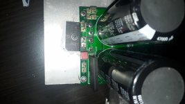
I've replaced bridge. I've left gnd lifter untouched. Still have 140v ac on vpos-vneg. Nothing changed.
Can anyone check if you have ac between these terminals?
Here are pics. But I've really looked for one hour with torch and glass to find any shorted solder, nothing found. I start to suspect c1 and c6, but those were last pair at Digikey. And pricey.
Rgrds.
Attachments
Last edited:
Clean up your PCB first... It's a mess!
With 140VAC (!) on the output you will likely see a nice firework from the capacitors... Also there must be something terribly wrong and building a sort of a voltage multiplier... Are you shure your DMM isn't broken or the battery is low?
With 140VAC (!) on the output you will likely see a nice firework from the capacitors... Also there must be something terribly wrong and building a sort of a voltage multiplier... Are you shure your DMM isn't broken or the battery is low?
- Home
- Amplifiers
- Solid State
- Hifisonix kx-Amplifier