The BOM was corrected by builder Anand so should be good. If you have problems during your build post them up here or up on the hifisonix.com webpage for the kx-Amp. Good luck with your build!
Thank YOU Bonsai for the design! Of note, ace builder “Vunce” used my corrected BOM and didn’t appear to have any issues. His build is on post #22.
Good luck with your build Rallyfinnen
Best,
Anand.
Good luck with your build Rallyfinnen
Best,
Anand.
Rallyfinnen, and Bonsai
I’m most of the way through a build and have made a few notes pertaining to the BOM.
- D4 and D5 need to be matched. Since these aren’t expensive, I bought 20. I got two nearly identical sets of matched pairs.
- For the fuse holders, the part number is for one piece. Since you need two per fuse, the BOM Qty should be 4 rather than 2 to hold the two fuses.
- For the output devices and drivers, consider if you want to use thermal pads. Same for the rectifier if you are building the ripple eater (and possibly the regular PS). I selected the following from Mouser: Small thermal pad 532-43-77-9 Qty 8, Large thermal pad 532-43-77-20 Qty 8, Rectifier thermal pad CD-02-05-REC-125-N. I believe that the output devices need insulating pads. If not using pads for everything, get some thermal compound.
- Consider what gain you want the amp to have as that determines the value of R25. I ended up using 15 Ohms in series with 7 Ohms (standing the resistors on end) so that I could switch between the two gains by shorting the 7 Ohm resistor out.
One thing I did was to create a searchable layout so that I could locate parts easier. Maybe I could post the PDF that I created?
I have some PCB assembly pictures taken along the way. I’ll try and post these soon.
For those who haven’t assembled PCB’s before, work from the shortest parts to the tallest. Makes for much easier soldering if you can flip the board over with a folded cloth on top of the components to push the parts up tight to the board.
I’m a very slow builder so I won’t have sound any time soon 🙁
Thanks for your notes Rocksteady. I’ll be doing some documents ration updates in the next few weeks and will add your points. Trust your build goes well!
Please feel free to post up Andy docs or pics here.
Please feel free to post up Andy docs or pics here.
Thank you for the tips!
Order is placed with Mouser now. Some adjustments needed from the BOM due to minimum order amounts and items out of stock, but the only thing I could not get was the spade connectors, but I think I have a few from before.
I also ordered some extra 0,2ohm emitter resistors, I have a feeling I would like to experiment with those.. or will it screw up bias stability or something else?
Is there a LTspice model available for the amp?
I would stick with the 0.33. Changing this - and especially lowering it - will require a lot of work with the bias controller. I would not do that.
🙂
🙂
Ok! 🙂
I have tried some simulation of the amp.. I'm not an experienced 'simulator', so there could be some things wrong here. I'm just looking at current sharing between upper and lower halves with different input levels, and it all seems fine in class A, but seems to get a bit unbalanced when it moves to class B? Maybe it is not relevant at all, or even normal, I'm just curious 🙂
I attach a graph of one upper and one lower emitter resistor and output voltage with 8ohm load.
Attachments

If that’s the emitter degen resistor current, then it’s not correct. Assuming a sine wave input, the output current will be a clean sine wave in class A and when it moves to class AB, you get the typical class AB half sine wave. There are some plots of this in the write-up.
Yes, the currents were from the emitter resistors, it seemed a bit strange to me too.
I have to check the schematic.
I used most of the models that comes with LTspice, except Q3-4, Q10-11 from Cordell and outputs models from Mouser. Maybe I should get all the models from Mouser on the components I ordered instead.
Sorry if this gets a bit off topic?
I have to check the schematic.
I used most of the models that comes with LTspice, except Q3-4, Q10-11 from Cordell and outputs models from Mouser. Maybe I should get all the models from Mouser on the components I ordered instead.
Sorry if this gets a bit off topic?
I could not find any faults in the model, so I don't understand the strange current sharing. Just for peace of mind, maybe I will measure it on the finished amps. I also tried simulating the OLG, and it indicates a lower -3dB point (I think it was abt 8kHz) than the documentation. Not sure if that's because of transistor models or something.
I'm trying to learn more about these simulations, that's why I do it.
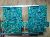
Components have arrived (but not PCB's), and I did some hfe measurements on transistors and also Vbe on the outputs. All but one good matches. I also did the zener-matching as mentioned above.
I have some thoughts on PSU. I don't think I have a suitable transformer, but I think I have two Onkyo transformers with 22V sec, that would be enough VA if I used both. Makes me want to do dual mono, but then I have to buy new caps. I have a pair of oversized caps that could do the job for a single PSU. Maybe two transformers and rectifiers feeding these caps, and the ripple eater after that.. I have to dig trough some boxes to see what I can put together at least for initial tests.
For some reasons I prefer dual PSU's.. maybe single PSU with dual ripple eaters would be another way of separating the supplies, but then the ground would still be common.
What do the experts say?
I'm trying to learn more about these simulations, that's why I do it.
Components have arrived (but not PCB's), and I did some hfe measurements on transistors and also Vbe on the outputs. All but one good matches. I also did the zener-matching as mentioned above.
I have some thoughts on PSU. I don't think I have a suitable transformer, but I think I have two Onkyo transformers with 22V sec, that would be enough VA if I used both. Makes me want to do dual mono, but then I have to buy new caps. I have a pair of oversized caps that could do the job for a single PSU. Maybe two transformers and rectifiers feeding these caps, and the ripple eater after that.. I have to dig trough some boxes to see what I can put together at least for initial tests.
For some reasons I prefer dual PSU's.. maybe single PSU with dual ripple eaters would be another way of separating the supplies, but then the ground would still be common.
What do the experts say?
I could not find any faults in the model, so I don't understand the strange current sharing. Just for peace of mind, maybe I will measure it on the finished amps. I also tried simulating the OLG, and it indicates a lower -3dB point (I think it was abt 8kHz) than the documentation. Not sure if that's because of transistor models or something.
I'm trying to learn more about these simulations, that's why I do it.
Components have arrived (but not PCB's), and I did some hfe measurements on transistors and also Vbe on the outputs. All but one good matches. I also did the zener-matching as mentioned above.
I have some thoughts on PSU. I don't think I have a suitable transformer, but I think I have two Onkyo transformers with 22V sec, that would be enough VA if I used both. Makes me want to do dual mono, but then I have to buy new caps. I have a pair of oversized caps that could do the job for a single PSU. Maybe two transformers and rectifiers feeding these caps, and the ripple eater after that.. I have to dig trough some boxes to see what I can put together at least for initial tests.
For some reasons I prefer dual PSU's.. maybe single PSU with dual ripple eaters would be another way of separating the supplies, but then the ground would still be common.
What do the experts say?
The 22VAC transformers will work well. I would rectifier and smooth each transformer secondary and then combine them to form the final PSU. You will have about +-29 to 29.5V DC out, maybe a bit less under load which should be ok.
Some build pictures
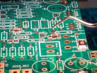
Finally getting around to posting some build pictures.
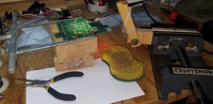
1) In general I tried to mount components based on their height off the board. So first off I mounted the surface mount caps. First is a picture of a dental pick holding down one of the small caps on the back side of the board.
2) Next is a picture of the jig that holds the pick. It worked fairly well, but tended to move the cap forward and backwards quite a bit.
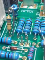
3) Next up is a picture showing most of the resistors mounted.
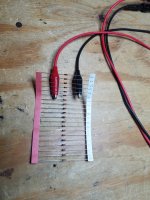
4) I ordered 20 Zener diodes for D4 and D5. I left them attached to the tape and numbered them. Then I measured each one and recorded the values. This allowed for easy matching to get two matched pairs.
5) Not knowing what gain I wanted, for R25 I used a 15 ohm resistor in series with a 7 ohm one, connecting them in midair. I left one lead of the 7 ohm resistor long and folded it back along the resistor body to allow for easy shorting out of the 7 ohm resistor to easily change the gain without changing parts.
Finally getting around to posting some build pictures.
1) In general I tried to mount components based on their height off the board. So first off I mounted the surface mount caps. First is a picture of a dental pick holding down one of the small caps on the back side of the board.
2) Next is a picture of the jig that holds the pick. It worked fairly well, but tended to move the cap forward and backwards quite a bit.
3) Next up is a picture showing most of the resistors mounted.
4) I ordered 20 Zener diodes for D4 and D5. I left them attached to the tape and numbered them. Then I measured each one and recorded the values. This allowed for easy matching to get two matched pairs.
5) Not knowing what gain I wanted, for R25 I used a 15 ohm resistor in series with a 7 ohm one, connecting them in midair. I left one lead of the 7 ohm resistor long and folded it back along the resistor body to allow for easy shorting out of the 7 ohm resistor to easily change the gain without changing parts.
Attachments
-
 5 R25 pair 20201004_150344.jpg540.1 KB · Views: 278
 -
 4 Measuring D4 and D5 candidates for matching 20200926_083143.jpg635.6 KB · Views: 335
 -
 3 Most of the short components mounted 20200725_082629.jpg1 MB · Views: 335
 -
 2 Jig to hold dental pick 20200718_101332 - cropped.jpg858.5 KB · Views: 338
 -
 1 Holding down SM cap 20200718_101151.jpg625.3 KB · Views: 344
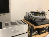
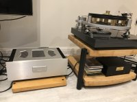
Just catching some Ali Farka Toure on the kx now.
The full class A Monty.
The full class A Monty.
Attachments
Last edited:
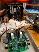
One channel assembled and powered up from regulated bench supply without smoke 🙂
Only using a small temporary heat sink and weak bench supply, so I only ran it in low Iq mode. I was able to adjust offset, and also saw some low level HF at output on the scope.
Only using a small temporary heat sink and weak bench supply, so I only ran it in low Iq mode. I was able to adjust offset, and also saw some low level HF at output on the scope.
Both amp boards completed. However, both seem to have oscillation of abt 400mVpp in the 100-200kHz area. Frequency varies with heat, and also jumps around when I touch the legs of the output transistors. If I connect a 7ohm load, frequency also jumps up a bit. This is with regulated bench supply and input shorted.
If I adjust the supply voltage, frequency changes too.
Suggestions?
If I adjust the supply voltage, frequency changes too.
Suggestions?
Attachments
- Home
- Amplifiers
- Solid State
- Hifisonix kx-Amplifier