Yes, I took a look. As you move closer to class B the bias spreader does modulate. This issue does not affect the output distortion since the current and voltage waveforms remain fully in class A per the spec - it’s only the output stage current between the two halves that are behaving like this.
To cure this, the bias spreader cap C5 (the one going C-E) can be increased to 100 uF while C16 can be reduced to 0.1 uF.
I will have look at this on my actual unit since the abov3 is a sim on my side, but for now, your amp should work to spec.
When you box it up, keep the PSU and Zobel wires from the module to the PSU short and twist the wires together. You should not see any ringing on the square wave tops.
Ok, thank you for the advice.
I actually tried a 8,2k (R42) resistor for the compensation too, and the edges of the square was a little bit more rounded, and the ringing reduced.
I don't have the correct coil on output either (probably higher inductance on mine), It's just something I grabbed from another amp. Not sure if it matters much.
I'm not too worried about the small ringing though.
I have looked again at the added cap option (C17), and I don't see any downside to it. It seems to have a lot more effect on the bias voltage stability than changing the other cap values. Just 10uF does a lot. I think it should be easier to just solder on a cap in this position, than to start messing with the smd caps. Could you try it in simulation and see what you think? Maybe I overlooked something (actually quite likely) 🙂
Last edited:
Do you mean C16?
Please wait until later today - I’m out for the next few hours. There are some other points I need to check.
Please wait until later today - I’m out for the next few hours. There are some other points I need to check.
Last edited:
Separately, if you want to operate the kx-Amp in straight Miller comp, just remove R42.
There is some anecdotal evidence that Miller comp sounds better than TPC (see comments of Hans Polak for example) but I have not tried a side by side comparison since all my amps have been TPC or TMC.
There is some anecdotal evidence that Miller comp sounds better than TPC (see comments of Hans Polak for example) but I have not tried a side by side comparison since all my amps have been TPC or TMC.
Wow, a full report! 🙂
I will have to look deeper in to it tomorrow to sort out what is what.
One thing popped to mind though: looks like traces are at 1kHz? Did you try lower frequencies? Something like 20Hz just below clipping into 4ohm to really put it to work 🙂
I will have to look deeper in to it tomorrow to sort out what is what.
One thing popped to mind though: looks like traces are at 1kHz? Did you try lower frequencies? Something like 20Hz just below clipping into 4ohm to really put it to work 🙂
Maybe I will try miller too, but I'm more interested in 2-pole, it seems more 'right' to me. I have done some experiments changing from miller to 2-pole on some other amps, and imagined the 2-pole sounded better, but maybe I was fooling my self to hear something better (easy to do when you buy something new, or modify something).
No, basically the same, but I think there was more variation in the bias voltage, likely due to higher impedance of the caps. The so called 'worst case'.
I decided to try a C17 cap and measure it. I just took what I had and it happened to be a 220u. I fed it with 20Hz a little below clipping (26V supply).
If you hover with the pointer over the pictures you can see the description in the file name.
I feel better using C17, but I will probably measure distortion with and without it later just to verify.
If you hover with the pointer over the pictures you can see the description in the file name.
I feel better using C17, but I will probably measure distortion with and without it later just to verify.
Attachments
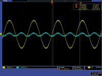
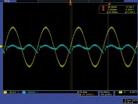
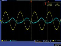
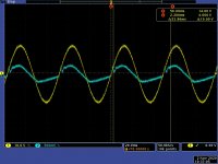

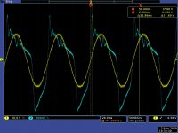
The yellow trace is always Vout.
Blue trace(diff probe):
Pic1 Bias voltage without C17
Pic2 Bias voltage with 220u C17
Pic3 Upper Re without C17
Pic4 Lower Re without C17
Pic5 Emitter to emitter voltage (upper and lower emitter resistors) without C17
Pic6 Same as above but with C17
Blue trace(diff probe):
Pic1 Bias voltage without C17
Pic2 Bias voltage with 220u C17
Pic3 Upper Re without C17
Pic4 Lower Re without C17
Pic5 Emitter to emitter voltage (upper and lower emitter resistors) without C17
Pic6 Same as above but with C17
I am assuming all of these pics are with the amp in class A.
It is definitely smoother with C17. If you are happy with It, then I’d just go for it. This is DIY 😉
In sims the distortion is unaffected by adding it, so it will be good to see what you get practically.
It is definitely smoother with C17. If you are happy with It, then I’d just go for it. This is DIY 😉
In sims the distortion is unaffected by adding it, so it will be good to see what you get practically.
No, this in 'low bias mode' because of limited heat sink I have on my desk. I guess I could do some short test in high bias mode too, and let it cool in between.
I have ordered some alu-profiles (to be used as adaptors) to be able to use some decent heat sinks when building the amp.
Anyway, it's DIY as you say, so I will play around with it for my own educational purposes (and since I don't have much to do at work with the current situation).
I have also started some simulation on the ripple eater, looking at output impedance.
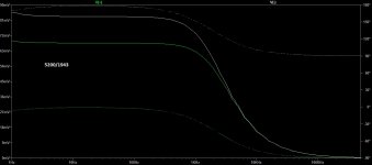
I tried some different 'outputs' (1943/5200) on that and found that it seems to reduce output impedance in the audio range (abt 130mOhm to abt 50mOhm AC) This was with abt 2A DC load. Could this be correct?
I also compared it to just rectifier and caps to get a reference.
I appreciate all the work you have done and shared, and the support! Thank you!
I have ordered some alu-profiles (to be used as adaptors) to be able to use some decent heat sinks when building the amp.
Anyway, it's DIY as you say, so I will play around with it for my own educational purposes (and since I don't have much to do at work with the current situation).
I have also started some simulation on the ripple eater, looking at output impedance.
I tried some different 'outputs' (1943/5200) on that and found that it seems to reduce output impedance in the audio range (abt 130mOhm to abt 50mOhm AC) This was with abt 2A DC load. Could this be correct?
I also compared it to just rectifier and caps to get a reference.
I appreciate all the work you have done and shared, and the support! Thank you!
Hi rallyfinen,
Sounds good.
The ripple eater output z is not as low as a regulated supply, but again, given the large 1000uF decouplers on the amp modules, I don’t think this is of any major consequence. It’s a few tens of milli- Ohms.
Sounds good.
The ripple eater output z is not as low as a regulated supply, but again, given the large 1000uF decouplers on the amp modules, I don’t think this is of any major consequence. It’s a few tens of milli- Ohms.
Last edited:
I've looked at the waveforms at 20 Hz this morning with the amp transitioning to class B. The output voltage waveforms are clean with and without C17. The simulated waveforms are very close to those that you actually measured.
However, at LF there is a significant improvement of the current waveforms (ie. they are very clean) through the degeneration resistors and the bias controller stand-off voltage, so indeed I think C17 = 100uF is a good improvement to this amp.
🙂
Here is a link to the .PDF http://hifisonix.com/wordpress/wp-content/uploads/2020/11/kx-Amp-Bias-Controller-.pdf
Attachments
Last edited:
Hi rallyfinen,
Sounds good.
The ripple eater output z is not as low as a regulated supply, but again, given the large 1000uF decouplers on the amp modules, I don’t think this is of any major consequence. It’s a few tens of milli- Ohms.
Do you mind if I post some simulations on that too? I know I'm being a difficult student again (just as in school) 🙂
🙂 Thought it's better to ask before I fill the thread with my simulations and stupid questions!
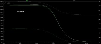
Anyway, I made a quick simulation with a resistor as DC load (abt 3A in this case) and a AC source with 1ohm impedance and 1V output in series with a big cap to simulate AC load. This should give the impedance of the 'output' where mV equals mOhm.
Below is what I did and what I found. Please correct me if the simulation method is wrong.
Pic1: Sim setup
Pic2: Bode plot of standard config
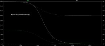
Pic3: bypassed (normal rectifier/caps)
Pic4: beefier outputs
Not sure of the reason for lower output impedance, if it's the more constant Hfe/current of the transistors, or what is actually giving the improvement. Maybe higher hfe on all the transistors would do the same?
BTW, the 1000u caps are giving the low impedance above 1kHz, without them the curve is pretty flat in the audio band.
Anyway, I made a quick simulation with a resistor as DC load (abt 3A in this case) and a AC source with 1ohm impedance and 1V output in series with a big cap to simulate AC load. This should give the impedance of the 'output' where mV equals mOhm.
Below is what I did and what I found. Please correct me if the simulation method is wrong.
Pic1: Sim setup
Pic2: Bode plot of standard config
Pic3: bypassed (normal rectifier/caps)
Pic4: beefier outputs
Not sure of the reason for lower output impedance, if it's the more constant Hfe/current of the transistors, or what is actually giving the improvement. Maybe higher hfe on all the transistors would do the same?
BTW, the 1000u caps are giving the low impedance above 1kHz, without them the curve is pretty flat in the audio band.
Attachments

Last edited:
- Home
- Amplifiers
- Solid State
- Hifisonix kx-Amplifier