I have played around more with my test setup today. Ripple eater are operational, and mid band 'buzz' improved a lot. There is still some 50Hz from ground loops. Also I have been fighting oscillation, and I'm starting to realize how sensitive this amp is to oscillation. Even after moving around ground points and strapping cables together I still had some sporadic oscillation. It seems I also get oscillations 'going around' in the ground loops created by the signal ground and power ground. If i disconnect one input ground, it quiets down. Since I'm not going to use the default setup with one PS and ripple eater for both channels, I can't build it according to instructions, so I'm on my own here. Had I ordered two ripple eater PCB's, I would have used them, but ordering another one takes too long, and gets too expensive with the VAT+handling fees (+ handling time) that are added to ALL packages arriving from outside EU to Sweden 🙁
I hope I can separate the two channels using two transformers, only having one common ground (incoming signal) and no ground loops. I don't have a grounded outlet in my living room, so no safety ground loop to worry about (only electric shock in case of a fault 🙂 )
I hope I can separate the two channels using two transformers, only having one common ground (incoming signal) and no ground loops. I don't have a grounded outlet in my living room, so no safety ground loop to worry about (only electric shock in case of a fault 🙂 )
Can you send me some scope shots of the oscillation? Is this with the standard two pole as in the build document?
Can you send me some scope shots of the oscillation? Is this with the standard two pole as in the build document?
Sorry, the scope I have at home cant even show these high frequencies properly, so no pics, and a wild guess would be that it is MHz range. This is with the standard 2P compensation. I don't worry to much, I think I will sort it out once I put some effort into it. The RC is still soldered on the amp boards, and I might have to play around wit the ground reference to the ripple eater too.
When I took the ground reference to the ripple eaters from the star ground, it was much worse, when I moved it to the amp boards, one channel was ok, but the other has some oscillation. Maybe the ripple eaters should be 'slowed down' too they don't need to 'eat' HF, only PSU noise.
Speaker grounds are also connected to the star ground at the moment, not to the amp PCB (as it was on this 'prototyping setup' from before).
If I remember correctly, disconnecting the load made oscillation stop, so the speaker grounds are another error source to try to move to the boards instead.
As you said before, this is a sensitive CFA amp, and I have not experienced this sensitivity before with my other builds (all VFA except JLH's I guess). I see it as a learning process, learning what is important might help me in the next project.
Since I don't follow your build guidelines, just let this be an example of why they should be followed, I'm not holding you responsible for my stupidity 😉
I'm actually a bit more confused now!
I'm had my sound card connected to the inputs of the amps, but not to the computer (USB sound card). Touching the RCA GND quiets the oscillation, and sometimes makes it go away completely. If I unplug the sound card from the amp, the oscillation is gone. So with inputs and input GND hanging in the air, there is no oscillation, and it all seems nice. I think this has to do with no interconnection between channels signal GND's.
I tried a cap from signal ground to heat sink on each channel, and that seemed to help when holding it in place with my hands, but then again after soldering some caps and wires in, with both inputs to the un-powered sound card, there was oscillation on one channel.
What I also saw before is that setting the DC offset on one channel makes the other channel DC go off.. there is some crosstalk somehow between channels, and it seems input GND related at least when it comes to oscillation. I think next I have to check signal GND and pwr GND is 33ohm on both channels. I think I at least narrowed it down a bit to something input-related.
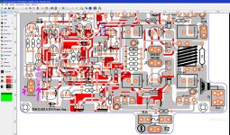
this R9 33Ω? I for some reason I add this faston GND just in case 🙂
Attachments
Last edited:
I have measured 66ohms between L & R signal GND. With both channels running high bias I have 3,2mV between L & R signal GND. If I connect them to each other (as a common unbalanced source), I get abt 25mV added DC offset on the outputs of the amp. Trying to correct one channel makes the other channel wander off.
This makes me think the GND point for the dc-offset adjustment should be PWR GND, not signal GND. Not sure how this affects PSRR.
This makes me think the GND point for the dc-offset adjustment should be PWR GND, not signal GND. Not sure how this affects PSRR.
I ran my sim changing the offset from 'optimal' (which was close to end position on the trimmer) to middle position on the trimmer, and the signal ground moved from +30mV to -29uV relative to the main GND. This voltage will most likely vary between channels IRL, and when the input grounds for two channels are joined together, there will be a 'crosstalk' between channels with different signal GND level.
I think in this case the hookup does not matter, the problem arises if both channels have the same PS GND, and the signal source has a common ground to join the input GND's for both channels. I guess if you are in luck, it would match for both channels, but I'm not that lucky.
I am actually a bit confused by the 33ohm (R9) resistor for the signal ground. I have added ground breaking resistors to some amps, but in that case the feedback ground point (R25) would also be connected to the input GND. In this case it looks like all the interference/diff that is presented on input GND will be amplified just the same as the input signal. If the feedback gnd is connected to the same point (signal gnd), they would cancel out not giving any output when the signal gnd level is moving. I guess that is not so easy here due to the low impedance of the feedback network?
Since my plan is to use dual supplies, I think I will remove R9. Maybe it would be just as good to remove it with single supply too? Not sure if it would do any difference to ground loop hum.
You could try joining/disconnecting your input GND's while measuring the DC out, I think you should see at least some little variation, depending on how well matched your channels are.
Last edited:
The feedback lower gain setting resistor (22 Ohms) was taken directly to power ground because the offset adjustment was done through the 33 Ohm HBR.
You should not remove the HBR. It’s there to stop cross channel loop currents which in an amp like this with high standing currents can be high if there are any loops inside the amp being cut by the transformer leakage flux (that’s why routing and twisting wires tightly together are so important).
You may get some interaction because the input grounds are joined at the input socket, but IMV a few mV is minimal. If you are not happy with this then better not to bond the signal grounds at the input socket.
My amp offset is about +-5mV after it’s warmed up.
Hi Bonsai,
Having been otherwise preoccupied on a RIAA/preamp construction I have returned back to the kX amplifier.
The previous (second) board using the 2SA/2SC output transistors together with BC "C gain" transistors has now been populated with "B Grade" BC transistors and the specified NJW output transistors. 100 nF has also been placed under-board across the dual input caps C9/C14.
I also purchased some 1.25mm wire for the coil (I was using 1mm) - just in case.
Unfortunately the oscillation continues in the 15 - 18 MHz region (this time at 17.4 MHz and 80 mV RMS).
Offset adjusted to < 1mV when warmed up.
The only thing I can now think of is if the value and type of C4 could have anything to do with it? (Panasonic ECEA1HN220U - 22uF, 50 VDC Bipolar - 5mm pin spacing) or R3 (where I've used a standard 3.3 Ohm metal film)?
Otherwise is there any way to lower stage gains in an attempt to prevent the oscillation?
Polsol, let me come back to you on this. Rallyfinnen had also reported problems so it looks like I need to revisit this and dial things back a bit. Please give me a few days.
🙂
🙂
Just as a reminder, higher value on R45 seemed to calm it down a bit when I was looking at the square wave flanks and small ring on the bench. (I think I used 8k just because that's what I had nearby). I did go back to the std value after the test, but that could be an easy fix to replace if it cures the oscillation.
Polsol has got IIRC c. 18 MHz and you have c. 4 MHz (can you confirm please).
18 MHz is unlikely to be loop stability, but more like parasitic oscillation. 4 MHz might be loop related, but it’s also high.
I have my unit on the bench and will look into it over the next few days.
(R45- do you mean R42 Rallyfinnen?)
18 MHz is unlikely to be loop stability, but more like parasitic oscillation. 4 MHz might be loop related, but it’s also high.
I have my unit on the bench and will look into it over the next few days.
(R45- do you mean R42 Rallyfinnen?)
Last edited:
I can't confirm the frequency since I can't se it on the cheap scope I use at home. It might be 4, it might be a lot more, I cant see the waveform, just a blurred 'mist' 🙂
Yes, R42, sorry. I actually tried to remove R42, and it even seemed to get slightly worse in amplitude, so I guess it's not loop stability in my case either.
I think I never saw it with the input disconnected (hanging in free air), but It comes and goes when both inputs are connected to an unpowered source (unplugged USB sound card). It can vary when I move around the input cables/sound card, and also when I touch the ground of the input, or touch components on the PCB.
When I power the amp, it does not start instantly, it starts after it reached full voltage and then some small delay. Maybe with heating of outputs? But I cant see how that relates to the apparent stability with input disconnected.
Last edited:
Rally
I tried 'snipping' R42 too as Doug Self in his power amp book had said that topology could cause instability but it had no effect.
Looking at the FFT on my scope I'm getting sub 0.01V (max precision on the FFT) at multiple frequencies but seems this is PSU artifacts/harmonics.
The main oscillation varies around 17.5 MHz at 60 mV RMS but there's another one at 7.7 MHz which fluctuates up to just over 10 mV.
Otherwise at some time bases the waveform is quite a mess - might be what you're getting too.
The above comments are with the input shorted of course.
BTW, on my LTSpice file I found using the BC spice models from LT I couldn't get the output 'zeroed' using R2 a&b. Switching to Bob Cordell's models for the BC's gave more satisfactory results.
Bonsai,
I have traced the 17 MHz signal all the way back to the transformer secondary with the kX connected (at about 10 mV RMS) at the rectifier connection. It's not there when the xK is not connected. Is this normal (sort of back reflectance of the oscillation)?
Or could it be the Transformer or rectifiers that is causing the issue?
BTW, this is without the Ripple Eater but there are 3 by 4,700 uF caps in 4 banks (2 sets of 3 each for pos and neg supply) - i.e. 12 in total.
To isolate this, try just loading the PSU directly without the kx-Amp connected. You may have ringing caused by the diodes and transformer leakage inductance as they come out of conduction. The cure for this is to snubber across the AC terminals of the rectifier - 47 Ohms and 0.1 uF located right at the rectifier will usually do the job. Your reservoir capacitors won’t get rid of this as the ESL and Trace inductance will probably be too high.
Re R42. When you remove this (or increase its value substantially) you are effectively converting from TPC to Miller compensation so indeed you will see different loop behavior.
Re R42. When you remove this (or increase its value substantially) you are effectively converting from TPC to Miller compensation so indeed you will see different loop behavior.
Last edited:
- Home
- Amplifiers
- Solid State
- Hifisonix kx-Amplifier