I see traces of the oscillation on the supply too (lower amplitude than on the output), but I think it's due to current drawn by the amp. Some cross conduction with the outputs working on such a high frequency maybe?
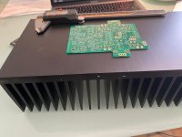
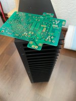
Boards arrived... heatsinks too large ?
Hi everybody
My PCB's finally arrived, and in my stock I "found" some old, and really heavy heatsinks. Size is 150mmX300mmX80mm (LXBXH)...
Are these too much for this amp ? I always struggle in sizing heatsinks. What I know out of the manual are the recommended specs...
Best,
Christoph
Hi everybody
My PCB's finally arrived, and in my stock I "found" some old, and really heavy heatsinks. Size is 150mmX300mmX80mm (LXBXH)...
Are these too much for this amp ? I always struggle in sizing heatsinks. What I know out of the manual are the recommended specs...
Best,
Christoph
Attachments
When room temperature is?
About 23C. I run the amp in class AA/B in the summer.
Rallyfinnen/Polsol,
Looks like I have isolated the problem to parasitic oscillation in the output stage. The loop is stable (although there is a bit of overshoot but this is easy to resolve and a separate issue).
I need to do some more tests tomorrow and friday and will come back to you with the fix.
Looks like I have isolated the problem to parasitic oscillation in the output stage. The loop is stable (although there is a bit of overshoot but this is easy to resolve and a separate issue).
I need to do some more tests tomorrow and friday and will come back to you with the fix.
I see traces of the oscillation on the supply too (lower amplitude than on the output), but I think it's due to current drawn by the amp. Some cross conduction with the outputs working on such a high frequency maybe?
Connected the PSU to the 8 ohm dummy speaker load I built and the PSU output looks clean.
No signs of oscillation in the region I'm getting amp oscillation.
The Earth line though is a different matter - full of junk.
Seems the oscillation in the PSU is related to that of the Amp oscillation itself, as Bonsai and you have mentioned, because of the current drawn.
Rallyfinnen/Polsol,
Looks like I have isolated the problem to parasitic oscillation in the output stage. The loop is stable (although there is a bit of overshoot but this is easy to resolve and a separate issue).
I need to do some more tests tomorrow and friday and will come back to you with the fix.
Take the time you need. Time to think and tinker/test usually result in a more elegant solution to a problem. Just out of curiosity, will you be adding the cap in the bias circuit too when you have it on the bench? Would be interesting to know if you can hear a difference before/after.
Polsol/Rallyfinnen,
can you solder directly on each module PCB a 10 Ohm resistor in series with a 0.1uF cap from the amplifier side of the output coil (ie the side closest to the 0.33 Ohm emitter degeneration resistors) to the 0V where it comes in on the PCB. You need keep the leads as short as you can make them.
Can you then tell me what you see on your scope.
Thanks
I always had this (RC to GND on the back of the PCB's) since I first tested the boards on the bench.
Polsol/Rallyfinnen,
can you solder directly on each module PCB a 10 Ohm resistor in series with a 0.1uF cap from the amplifier side of the output coil (ie the side closest to the 0.33 Ohm emitter degeneration resistors) to the 0V where it comes in on the PCB. You need keep the leads as short as you can make them.
Can you then tell me what you see on your scope.
Thanks
I don't have a spare 10 ohm 5W resistor handy but can pick one up tomorrow.
Would connection using the ZN output and and OV tabs on the kX board suffice or do you want it closer?
I don't have a spare 10 ohm 5W resistor handy but can pick one up tomorrow.
Would connection using the ZN output and and OV tabs on the kX board suffice or do you want it closer?
I don't think that a 5W resistor needed.
2W is fine.
If 1/4w is used you know better what happen. 😉
Hello all. I just got my first channel running, and it too had an oscillation around 16 MHz. Good news is that the 0.1 uF and 10 Ohm resistor emiminated it.
I had and old 2W carbon resistor and 0.1u cap. Soldered them together and pressed the leads down into the top of the 0V and Zn quick disconnect connectors. Crude, not tiny by any means, but it did the trick.
I had and old 2W carbon resistor and 0.1u cap. Soldered them together and pressed the leads down into the top of the 0V and Zn quick disconnect connectors. Crude, not tiny by any means, but it did the trick.
I'm thinking of using something like this so that I can add the RC components w/o having to remove the board from the heat sink.

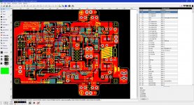
rocksteady can you put pictures of what you did? I'm making my own diy board from the data that Bonsai provide and yes I know is "only for personal use not for sale I agree on that 🙂 ", I'm gonna check all one more time just to be sure all is 100% correct I just found a few errors on the kx-maplifier and I need to check the PSU too
"I had and old 2W carbon resistor and 0.1u cap. Soldered them together and pressed the leads down into the top of the 0V and Zn quick disconnect connectors. Crude, not tiny by any means, but it did the trick."
"I had and old 2W carbon resistor and 0.1u cap. Soldered them together and pressed the leads down into the top of the 0V and Zn quick disconnect connectors. Crude, not tiny by any means, but it did the trick."
Attachments
I had and old 2W carbon resistor and 0.1u cap. Soldered them together and pressed the leads down into the top of the 0V and Zn quick disconnect connectors. Crude, not tiny by any means, but it did the trick.
I see variations in the oscillations when touching stuff, so it could be a good idea to solder them in and re-check.
Vargas, My idea wasn't practical as there's not sufficient room for 4 crimp connections, so I'm thinking that soldering the RC components on the back of the amplifier board may be the best way to go (as Rally mentioned).
- Home
- Amplifiers
- Solid State
- Hifisonix kx-Amplifier