Not if you use a CCS for the LTP. Also, cathodyne's output signal source is not strictly symmetric, one comes from the plate, the other from the cathode. Nitpicking, I know 🙂On the plus side, Cathodyne has a more balanced output into the 6AS7 power stage

I mentioned above using a MOSFET as Phase Inverter: That will save me some filament current load 🙂 and potentially give me a better voltage swing?
See attached as an example circuit. Credit: https://wtfamps.com/2018/10/31/solid-state-phase-splitters/
The author comments on the MOSFET use allowing voltage swing much closer to the rails.
See attached as an example circuit. Credit: https://wtfamps.com/2018/10/31/solid-state-phase-splitters/
The author comments on the MOSFET use allowing voltage swing much closer to the rails.
Attachments
Cathodyne needs to "split" the B+ voltage, for each output channel. LTP uses full B+ for each channel.
In my opinion (and probably many will disagree) cathodyne is good for easy to drive, low/medium power tubes, like EL84, 6V6 , ECL86 etc. For anything requiring a swing of 60Vpp or higher I use LTP, preferable with a CCS.
Using a negative supply allows the LTP using as much B+ as possible, yes.
In my opinion (and probably many will disagree) cathodyne is good for easy to drive, low/medium power tubes, like EL84, 6V6 , ECL86 etc. For anything requiring a swing of 60Vpp or higher I use LTP, preferable with a CCS.
Using a negative supply allows the LTP using as much B+ as possible, yes.
Perfect explanation: LTP it has to be to get the voltage swing (6AS7 is low Mu, close to unity in practice I understand).
That is, assuming you only have 290V for the splitter to play with.Perfect explanation: LTP it has to be to get the voltage swing (6AS7 is low Mu, close to unity in practice I understand).
I use a Cathodyne phase splitter to drive directly a set of 3x 6080WA in OTL configuration, for 10W/RMS output, similarly to the schematics I posted :


No issue at all... Despite what some "knowledgeable" guys argue... Limit taking me for an imbecile.
T
No issue at all... Despite what some "knowledgeable" guys argue... Limit taking me for an imbecile.
T
Last edited:
Yeah, but what supply voltage and bias do you have going on in there?
I've used the concertina to successfully drive the 6AS7G, 6n13s, 6336, etc- but not at ~150 volts peak swing.
I've used the concertina to successfully drive the 6AS7G, 6n13s, 6336, etc- but not at ~150 volts peak swing.
@tubelectron - lovely looking set of monoblocks there. Something to be proud of I'm sure 🙂
Is that your pic on the label? Stylish.... 👍
Is that your pic on the label? Stylish.... 👍
Yeah, but what supply voltage and bias do you have going on in there?
I've used the concertina to successfully drive the 6AS7G, 6n13s, 6336, etc- but not at ~150 volts peak swing.
Oh, I let those "knowledgeables" guys and "aces of simulation" guess... 😉
And a Concertina is this for me - I don't use it in my amps 😆 :
@tubelectron - lovely looking set of monoblocks there. Something to be proud of I'm sure 🙂
Is that your pic on the label? Stylish.... 👍
Thanks @Mission720 ! 🙂
No, it's not my picture on the label 😀 : it's Mr. Julius Futterman 's portait, as a tribute to his genius... 😎
Some other pictures while we are at it :
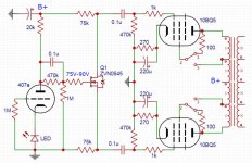
Look at how simple is the wiring of the input preamp + phase splitter section. The potentiometer acts as a fine tuning for the direct coupling between input preamp and Cathodyne phase splitter :
Possibly not an enough complex or wealthy design ? 🤔
T
Last edited:
Cool - I do like simplicity, although a degree of "complication" might get me better efficiency.
I will progress the LTP setup, with various options in mind.
My main aim with this is to use an existing chassis (of which I now have 10, having sold off a good number!)
I will progress the LTP setup, with various options in mind.
My main aim with this is to use an existing chassis (of which I now have 10, having sold off a good number!)
Cool - I do like simplicity, although a degree of "complication" might get me better efficiency.
I will progress the LTP setup, with various options in mind.
My main aim with this is to use an existing chassis (of which I now have 10, having sold off a good number!)
Fine ! You do what's best for you... 😉
With the LTP - I suppose that it means Long Tail Phase Splitter 🤔 - you have an additional time constant wich can be detrimental to low-end extension and stability, and show noticeable phase shift errors in the treble range.
This doesn't exists in the Cathodyne, which represents a great advantage for an OTL amplifier. Below, the square waveform output at 4Hz and 40kHz of my OTL amps, at 10WRMS output :
T
Attachments

An OTL amplifier has nothing to do with a push-pull , output voltage for 8ohm is a few volts so drive is low too .
Anyway , a knowledgeable guy should know what max voltage should expect from a cathodyne .
Anyway , a knowledgeable guy should know what max voltage should expect from a cathodyne .
The LTP is a Long Tail Pair (also known as Differential Phase Splitter). It's more complicated than other phase splitters but the advantage in my situation is the voltage swing.
We all have our favourite circuits and particular amplifiers, especially ones we have made and to which we become emotionally attached.
Thanks to all who have made the effort to contribute. This is a wonderful community and site for sharing and conversing.
We all have our favourite circuits and particular amplifiers, especially ones we have made and to which we become emotionally attached.
Thanks to all who have made the effort to contribute. This is a wonderful community and site for sharing and conversing.
I have also seen schematics for an LTP using a Pentode/Triode (specifically ECF82) which greatly improves the HF performance.
See attached, credit: http://www.r-type.org/articles/art-097.htm
My choice of 6N1P stems from the fact that I have a big box of them, being -EV type and NOS. I also have a box of about 50 brand-new 6AS7G NOS which look absolutely stunning.
I don't have any ECF82, but they are reasonably available on flea-bay.
Attachments
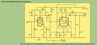
The linked article is an interesting read:
"The long-tail circuit shown above is well known and widely used but the fact remains that its HF response is relatively poor. This cannot be due to the second half of the valve as this section is effectively driven as a grounded-grid amplifier. The trouble is due to the first half of the valve and is due to that hardy perennial-Miller effect. The gain of this first valve is effectively halved due to the input impedance at the second valve cathode. Even so the Miller capacitance is quite large and certainly cannot be neglected. In order that some estimated value of frequency response can be obtained, some typical values will be taken. Using the ECC83 as a typical valve, the quoted anode-to-grid capacitance is 1.6 pF so the total value will be certainly as large as 2.0 pF when wiring and valve-base capacitances are taken into account. The gain of each half of the valve can be as much as 60 times, but this would be better reduced to a factor of 50 as there is a supply voltage loss in the common-cathode resistor. The overall gain will therefore be about 25 times when used in this phase-splitter. This will give a reflected Miller capacitance of approximately 50 pF, so the total capacitance loading on the previous stage will be about 60 pF if 10 pF is allowed for all other capacitances. With a 100 kΩ source impedance this will give a -3 dB point at about 25 kHz, and this is clearly not good enough when output transformers with primary resonance's of about 150 kHZ are considered. The phase shift of the amplifier circuits must be as small as possible where the output transformer reaches its first primary resonance; and therefore the bandwidth of this type of phase-splitter can easily degrade the total amplifier performance. The use of a step network across the anode load resistor of the driving valve can help in this matter, but only If the step starts well before the natural fall-off frequency of the circuit itself. In the case just considered this would mean starting the fall-off of amplifier gain by the step network at approximately 2.5 kHZ or lower. This would obviously give excessive reduction in loop gain at the high frequencies, with consequent increase in distortion.
The answer therefore lies in producing a fall-off at the HF end of the spectrum that starts at a much higher frequency. This could be attempted by reducing the value of the output impedance of the previous stage. This could be done by negative feedback with consequent gain loss; or alternatively by using a smaller value of anode load resistor. This latter also gives a severe loss in gain, quite apart from the increased noise that is produced by the increased valve current. The answer was therefore seen to lie in producing a phase-splitter that did not give the large input capacitance of the previous circuit.
Circuits are known [5] that do give good HF response in phase-splitter service, but they suffer from high cost due to the complexity of the circuitry involved. The circuit that was finally evolved (see below) has a cost that is only slightly more than that of the conventional circuit, but has a greatly improved response at high frequencies.
Basic circuit of modified long-tailed-pair phase-splitter:
The operation of the new circuit is just about identical with that of the conventional long-tailed pair except that the first valve is a pentode. This reduces the Miller effect to negligible proportions and increases the total bandwidth by a factor of just under ten times. Even allowing that the gain of the circuit is about 2 dB less than the conventional circuit, this still gives a gain/bandwidth improvement of about seven times. The comparative gain/frequency plots are shown below, where it is seen that the final rate of fall in both cases is identical at 20 dB per decade. This indicates an ultimate phase shift of 90 degrees which was borne out by measurement."
Since he needs comparable high voltage swing he will need more than 290V Ub, thats a fact, so, in any case Ub has to be increased .
An other fact is, he has loads of 6n1p, and wants to use them. But even when run at higher voltage, a Ltp with those tubes would be hard pressed to deliver the required drive voltage.
But the same tube, if casoded, could share the load, and provide whitout a swet what is needed.
May i suggest the following:
First 1/2 6n1p, in so called grounded cathode, anode at 80V feeding directly the grid of the second 1/2 6n1p, wich would be a 50/50 split loaded, so called concertina.
The concertina outputs are capacitive coupled to the differential cascode (a pair of 6n1p cascodes).
A total of three 6n1p and a simple fullwave voltage doubler (1 extra rect bridge, some caps, resistors and zeners for safety) would be needed, but hey, he asked about the "best" design options, so i tried to give what he asked for.
ECC83 ( the weakest triode ) is not typical , especially for LTP . I didn't see any lack of high frequency with other tubes .
- Home
- Amplifiers
- Tubes / Valves
- HiFi phase splitter - "best" design option?