@jcalvarez Thank you for the SIM - looks like 10w with low distortion is quite achievable 🙂 and that's without a negative supply?
I'm wary of this growing into a monster (with a monster budget), however if there's a great benefit for a minor outlay I'd be daft not to consider.
I'm wary of this growing into a monster (with a monster budget), however if there's a great benefit for a minor outlay I'd be daft not to consider.

Yes, using the LM334 is possible to avoid the negative supply, but (as usual, there is a but):
1) It is borderline, the minimum voltage required by the LM334 is 1V, and with an input signal bigger than 0.5v it goes out of the working zone in the peaks.
2) I had to use a low current for the LTP in order to have a bias voltage of 4.5V to make the CCS work. I'd use a different tube with higher gm for the LTP, to have a bigger driving current while still having enough bias voltage. Maybe ECC88/6H23P.
Adding a small negative supply will make it easier to tune, and also use a simple bipolar CCS instead of the LM334.
I have some 6N23P around: I was going to use them for a Cascode pre-amp stage feeding an EL34 or similar for a SET. For that, I can use exactly the same chassis I'm using for the 6AS7 setup. I got a reasonable deal for 10 sets of the chassis, mirror stainless steel finish with all the fixings such as valve bases, phono RCA input connectors and speaker o/p posts, fused power input connector.
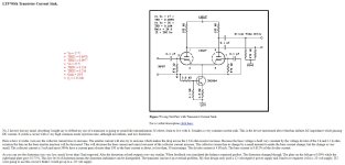
This is an interesting CCS for an LTP. Just uses a single transistor and produces a very low distortion level. It requires a negative voltage of -20v in the attached diagram, however the author suggests that -30v would yield a better design/result. Looks like I've only got -16vdc to play with if I have 25vac from the power Tx. So, that Vigortronix at 24vdc is looking attractive (there's a 48vdc version too....)
Credit for attachment: https://www.angelfire.com/electronic/funwithtubes/Amp-DB_Heart.html
Credit for attachment: https://www.angelfire.com/electronic/funwithtubes/Amp-DB_Heart.html
Attachments
that will work, but a cascoded version will work much better. Something like the one here is my usual-

Here is a simple, well-known, efficient phase splitter design principle : 1st stage in direct coupling to a second stage in cathodyne phase splitter,

This principle was used in a number of amps, notably by Dynaco :


I used this very simple principle on many of my DIY amps with success... Stable and reliable, no time-constant, easy to NFB , not really tube-critical, low distortion due to the direct coupling of the 1st stage to the second (no extra-load to the plate, no phase shift, maximum gain available for the plate load) , and the distributed loads of the phase splitter (gain circa 1).
T
This principle was used in a number of amps, notably by Dynaco :
I used this very simple principle on many of my DIY amps with success... Stable and reliable, no time-constant, easy to NFB , not really tube-critical, low distortion due to the direct coupling of the 1st stage to the second (no extra-load to the plate, no phase shift, maximum gain available for the plate load) , and the distributed loads of the phase splitter (gain circa 1).
T
Last edited:
The problem is delivering 180V vpp from 290 B+. Not sure a cathodine can do that.
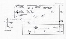
Here is a trick negative PS for an NPN drain on a diff amp I used a while back.
Current pulses across R11 the HV supply return lead cause pulses of voltage rectified by D3.
Those stored in C112, filtered by R112 & applied to the zener Z7.
Further smoothed by C105. 👍
Current pulses across R11 the HV supply return lead cause pulses of voltage rectified by D3.
Those stored in C112, filtered by R112 & applied to the zener Z7.
Further smoothed by C105. 👍
Attachments
Cathode bias on 6AS7 is going to waste a lot of heat and HT . It's a questionable valve for audio from my experience , not usually the best match between sections and needs a lot of drive volts , The only advantage I can think of is the low turns ration output transformer , mains toroids can be used . I would strongly suggest punching a pair of holes in the chassis or will be stuck with a single output valve
The cathode resistors will drive the plate currents towards a better match than possible with fixed bias.Cathode bias on 6AS7 is going to waste a lot of heat and HT
Better if they are heat sinked resistors to the chassis.
Cathode bias on 6AS7 is going to waste a lot of heat and HT
If we follow that argument we should not be building tube amplifiers at all. 😀
The way I see it, most of my critical, long listening sessions happen during the winter, in which case it costs me money to heat my living space anyway. 🙂
I suggest a voltage doubler feeding your phase splitter with the max voltage that tube can take, otherwise you will have a hard time driving the output. You will have to drop the doubled up voltage with a serial resistor and a string of zener diodes to 400V or so. Four 100V 5W zeners and some low voltage, 400-1000mW, zener in serial should do. The voltagedrop over the low voltage zener would provide positive grid voltage for the splitter so your current source would have some voltage to work with. Also, your output tubes have almost certain a differing ac input voltage requirement to deliver ac balanced output, so it would be good to have some adjustable anoderesistors in the splitter (anode resistors connected to the ends of a pot, pot slider connected to upper end of zener string, both sides of the pot bypassed by resistors for safety). Also, to make the opt happy, a dc balance pot (with bypass resistors for safety!) in the cathodes of the output would be a good idea.
Last edited:
My idea is using a PP - PP interstage. The driver tube can be 6DJ8 in differential mode having CCS at common cathode. This will produce very clean driving signal for the following stage. Also, the input can be either SE or balance.
Johnny
Johnny
Of course is out of question , but some people don't read just post 🙂
Thank you, I can read. 63V RMS at the grid of a 6080 ? 😆
T
Please expand this. What do you mean ?Of course is out of question , but some people don't read just post 🙂
The same approach will work without a negative rail, I suspect this would be the ideal option for the OPThis is an interesting CCS for an LTP. Just uses a single transistor and produces a very low distortion level.
Credit for attachment: https://www.angelfire.com/electronic/funwithtubes/Amp-DB_Heart.html
Hi - thanks for your comment. I understood that a Cathodyne PI has a lower voltage swing potential compared with LTP PI and what the 6AS7 needs is a large voltage swing. On the plus side, Cathodyne has a more balanced output into the 6AS7 power stage.Using a cathodyne for this power stage , obviously
Thanks for the comments 🙂In case you want to drive 6AS7G's with a phase splitter, then you have just one choice; the LTP. With or without bootstrap from the UL-taps of output transformer.
250...290 V is far from optimum. The optimum anode voltage of 6AS7G is 250 V (max. suggested by specs.). Cathode bias require some 120...125 V, so +Ub should be 370...380 V. Then each triode-halve will take 50 mA.
12 W is possible, but required drive voltage is 250 Vp-p (i.e. 2 x Ubias)
For best linearity (lowest THD), take 5k output transformer.
That is a good idea. 6AS7G has inherently quite high 3rd harmonic distortion (in PP).
LTP seems the best option for preserving voltage swing, the OPTs I have don't have UL taps.
I have a limited range of B+ derivable, but there is also a 220v and 240v option for primary, so I could use 220 connections as local supply is 230vac to get a bit more of a voltage boost.
The OPTx is have are 3.5k so I guess I'll have to live with that for the time-being...
- Home
- Amplifiers
- Tubes / Valves
- HiFi phase splitter - "best" design option?