Depanatoru, yes, ecc83 is mostly to weak for a ltp,, but he has 6n1p, Rp ca. 8k at 7mA, mu 35.
The 6n1p is not really a equivalent to ecc88, as often advertized, but quite useable
The 6n1p is not really a equivalent to ecc88, as often advertized, but quite useable
Last edited:
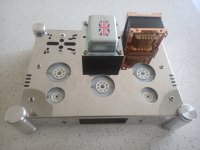
Hi - thanks for the suggestion. There is a limitation associated with my "pile" of 6N1P-EVs and that is the existing chassis. Photo below. Its a lovely chassis with mirror stainless steel finish. It's used in an EL34 SET usually, but I thought why not try a 6AS7G in there.Since he needs comparable high voltage swing he will need more than 290V Ub, thats a fact, so, in any case Ub has to be increased .
An other fact is, he has loads of 6n1p, and wants to use them. But even when run at higher voltage, a Ltp with those tubes would be hard pressed to deliver the required drive voltage.
But the same tube, if casoded, could share the load, and provide whitout a swet what is needed.
May i suggest the following:
First 1/2 6n1p, in so called grounded cathode, anode at 80V feeding directly the grid of the second 1/2 6n1p, wich would be a 50/50 split loaded, so called concertina.
The concertina outputs are capacitive coupled to the differential cascode (a pair of 6n1p cascodes).
A total of three 6n1p and a simple fullwave voltage doubler (1 extra rect bridge, some caps, resistors and zeners for safety) would be needed, but hey, he asked about the "best" design options, so i tried to give what he asked for.
The Power TX is made by Primary Windings in UK, specifically without 5v winding as the intention was always to use SS rectification.
The OPT is a 15w PP at 3.5k. It's deliberately fitted "upside down" since it will have a cover over it (base carrier also fitted) and that gives me more space at the top to connect and route wires back underneath.
The chassis has had a letterbox cut out at the front to take a bluetooth/FM tuner/SD card/USB/Aux connection module to add versatility. I have already used one and I must say I was greatly impressed! Comes with remote control too.
So, I have 3 octal sockets and 2 noval sockets. Hence, one 6SL7 to provide pre-amp for each channel, a 6N1P-EV either side as phase splitter and finally 6AS7G for PP power stage.
PS - that chassis is nearly impossible to work on. I had to drill two new holes for the OPT cover base and you can see how even a cobalt drill bit just work-hardened the chassis on the vacant side. I got there is the end...
Attachments
Last edited:

I have heard similar comments about Chinese steel chassis, one guy said "feels like they use depleted uranium" 🙂PS - that chassis is nearly impossible to work on. I had to drill two new holes for the OPT cover base and you can see how even a cobalt drill bit just work-hardened the chassis on the vacant side. I got there is the end...
And the annoying thing is, there are soooo many options with the holes and slots provided, however absolutely nothing lined up!I have heard similar comments about Chinese steel chassis, one guy said "feels like they use depleted uranium" 🙂
Ok, than there really are not many options left, use a LPT and prop up the Ub with the fullwave doubler/zener arrangement I descriped earlier. If you need some more swing (headroom) than the 6N1P can deliver, a E182CC can.Hi - thanks for the suggestion. There is a limitation associated with my "pile" of 6N1P-EVs and that is the existing chassis. Photo below. Its a lovely chassis with mirror stainless steel finish. It's used in an EL34 SET usually, but I thought why not try a 6AS7G in there.
The Power TX is made by Primary Windings in UK, specifically without 5v winding as the intention was always to use SS rectification.
The OPT is a 15w PP at 3.5k. It's deliberately fitted "upside down" since it will have a cover over it (base carrier also fitted) and that gives me more space at the top to connect and route wires back underneath.
The chassis has had a letterbox cut out at the front to take a bluetooth/FM tuner/SD card/USB/Aux connection module to add versatility. I have already used one and I must say I was greatly impressed! Comes with remote control too.
So, I have 3 octal sockets and 2 noval sockets. Hence, one 6SL7 to provide pre-amp for each channel, a 6N1P-EV either side as phase splitter and finally 6AS7G for PP power stage.
PS - that chassis is nearly impossible to work on. I had to drill two new holes for the OPT cover base and you can see how even a cobalt drill bit just work-hardened the chassis on the vacant side. I got there is the end...
The supply voltage will still limit the available swing, even if going to a different tube like the E182CC.
Unless you increase the supply voltage or choke load the differential plates there isn't much else you can do here.
Unless you increase the supply voltage or choke load the differential plates there isn't much else you can do here.
Could I play around with the Cathode bias of the 6AS7G, ie to increase current flow? With the same voltage swing would that get me a higher power?Unless you increase the supply voltage or choke load the differential plates there isn't much else you can do here.
I'm sort of thinking Ohms Law here, but obviously there's the OPTx to consider as well...
If you increase the current through the 6AS7G you will need less bias for a given plate voltage, but you will get into dissipation concerns quickly in order to get the bias down any significant amount without reducing the plate voltage. Lower plate voltage will reduce maximum output capability if you bias it hotter to make up for it.
Trade offs everywhere.
Trade offs everywhere.
So, stick with LTP for the swing, a CCS on LTP for balance, a negative supply on bottom of CCS for greater headroom, and as high a B+ voltage as I can get without exceeding ratings.If you increase the current through the 6AS7G you will need less bias for a given plate voltage, but you will get into dissipation concerns quickly in order to get the bias down any significant amount without reducing the plate voltage. Lower plate voltage will reduce maximum output capability if you bias it hotter to make up for it.
If you are feeling adventurous, use a small push-pull transformer instead of the LTP plate resistors. That will give you a lot of driving voltage to play with.
For some reason I always liked amps with concertina phase splitter. Not Hifi per se but real-fi to me🙂
Nothing wrong with concertina for Hi-Fi, and it has some advantages when compared to LTP, gain being one of them. It is just the specific use case here, low B+ and high driving voltage requirement makes it impossible to use it unless we increase the supply voltage significantly.For some reason I always liked amps with concertina phase splitter. Not Hifi per se but real-fi to me🙂
I've not come across that sort of wizardry before. Do you have some (practical) circuit examples? Was this used in any commercially produced hi-fi amps?If you are feeling adventurous, use a small push-pull transformer instead of the LTP plate resistors. That will give you a lot of driving voltage to play with.
With the voltage doubler i mentioned (several time) he has almost 600V at disposal, the e182cc can swing much more than a 6n1p ever couldThe supply voltage will still limit the available swing, even if going to a different tube like the E182CC.
Unless you increase the supply voltage or choke load the differential plates there isn't much else you can do here.
I've seen it mentioned in the forum, also did some simulations, works pretty well. But I have never seen a real amplifier using such arrangement. To be honest you do not need it, and it will be a not so small additional cost.I've not come across that sort of wizardry before. Do you have some (practical) circuit examples? Was this used in any commercially produced hi-fi amps?
Regarding the voltage swing a choke would give you that. But who would want the added cost and troubles of an additional inductance in an amp with overall fb just to avoid propping up Ub? So, after the invention of fb, there wont be many amps with chokes in the anodes of the driver. Transformer coupling would make more sense, because you would get rid of the otherwise needed cap and have the advantage of a low dcr grid circuit (would avoid tube runaway with fixed bias). But stuff like that, can usually only be found in high power, high efficiany class B amps, not in smallish hi-fi amps.
If, for whatever reason, Ub does not get the proper lift needed, one could, before going on any expensive choke or transformer adventure, use the inductance allready there, the OPT. Boostrapping the Ltp from the Opt can be done easely, but non of this will give as good, and predictable, results as lifting Ub up to what is needed or limited by the tube.
If, for whatever reason, Ub does not get the proper lift needed, one could, before going on any expensive choke or transformer adventure, use the inductance allready there, the OPT. Boostrapping the Ltp from the Opt can be done easely, but non of this will give as good, and predictable, results as lifting Ub up to what is needed or limited by the tube.
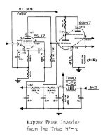
Why not to try with Kappler PI ? , it is one variant of Concertina PI where both output is low impedance , good to drive 6AS7 triode grids in A1 class where of course this posted schematic need B+ to be scaled up to around 400V- 450V , so that the values of the other passive elements must also be changed in accordance with the higher B+ and eventually with other tube types used.
Attachments
Last edited:
Not enough swing, and horrible overload effects.Why not to try with Kappler PI ? , it is one variant of Concertina PI where both output is low impedance
Merlinb
Will there be an improvement in the Kappler circuit's characteristics if let`s say, only the phase inverter part (6SN7) is powered with bipolar +/- 250V ? , while input 6SJ7 only with +250V ? .
Will there be an improvement in the Kappler circuit's characteristics if let`s say, only the phase inverter part (6SN7) is powered with bipolar +/- 250V ? , while input 6SJ7 only with +250V ? .
That would solve the swing problem, but not the overload concerns. It's just not good practice to load a cathodyne PI with unequal loads. It already has very low output impedance provided it is equal loaded (2/gm for both outputs).Will there be an improvement in the Kappler circuit's characteristics if let`s say, only the phase inverter part (6SN7) is powered with bipolar +/- 250V ? , while input 6SJ7 only with +250V ? .
- Home
- Amplifiers
- Tubes / Valves
- HiFi phase splitter - "best" design option?