Base level performance assessment - do the heaters finally operate at 6.3V continuous?
It sounds like you find some time delay for a few hiccups is not acceptable for the heaters, but it is acceptable for the B+ to be delayed by some timer that goes out to 30 seconds? Is it the extra extra time delay before music starts, or is it the aesthetic that there are surreptitious hiccups going on with the heater powering soon after turn-on?
Perhaps re-read what I said about the B+ filter cap - it is only the first filter cap where the smps has a problem. The smps doesn't need 220uF to provide a stiff regulated 300Vdc. If the B+ is stiff, then crosstalk is not a concern for the output stage - maybe that is where you are misinterpreting how the amplifier will perform - there is no common B+ capacitor that sags from one channel's load in between when the 100Hz charging pulses top the cap voltage up.
The B+ supply to any line stage/tone/buffers are not an issue, or need to change, as they are fed from typical RC filtering. The subtlety now is that the RC filter sections provide just local decoupling and voltage level control, and don't need to be sized for mains ripple attenuation.
Last edited:
There is no "first filter cap" then. What you see is what I was doing. There was no "CRC" filter, just "RC" and R was rather large for a tube amp.
Also, I didn't design it and if I had, there would by no delay on B+. In theory, I can short the timing resistor on the 555 to eliminate it? Then the PSU will at least start eventually. The PSU tried to start after the delay, then tripped out, but by that time the bleeder resistor did it's job so the PSU trips again. If the delay wasn't there it would trip a few times and then latch up.
Ideally the PSU will turn on and work the first time. If you bought a television that had to turn on and off several times before it actually started working, you'd return it.
As I understand it, you added 620R/220uF per channel - that means the initial charge current through each 620R is at least 300V/620 = 0.5A, so at least 1A is required from an output rated at 0.6A - go figure.
I suggest just connecting both channel output stages directly to the 300V smps terminals directly, as the smps is a stiff supply, even though the small amount of 300Vdc filter capacitance on the smps pcb is causing heart palpitations for you.
I suggest just connecting both channel output stages directly to the 300V smps terminals directly, as the smps is a stiff supply, even though the small amount of 300Vdc filter capacitance on the smps pcb is causing heart palpitations for you.
For SMPS for heaters rate the supply at twice the heater current rating is recommended. This ensures it does start when the heaters are cold. Most SMPS will retry on startup.
As I understand it, you added 620R/220uF per channel - that means the initial charge current through each 620R is at least 300V/620 = 0.5A, so at least 1A is required from an output rated at 0.6A - go figure.
Yes, for a few ms. Then it still failed after it was through a 100mA current limiting MOSFET. I think you mentioned phase angle on the charge pulses or that was George.
Once again, shouldn't it be able to deal with the inrush? Imagine a 1N4007 blew up at exactly 1001mA? What a stupid concept.
Last edited:
Perhaps provide a schematic, as the 620/220uf was described back in post #37. Prior to that was 500/500uf, which is at least 0.6A. Staying under the spec seems appropriate.
Maybe my problem relates to my understanding of passive supplies. Any "normal" PSU will deal with temporary overcurrent. My A/C has a good peak inrush of probably 30A. A normal fuse might start it most of the time, but a slo-blo will start 100% of the time, and a fast acting fuse will not allow it to start ever. The supply will never decide it "can't do it, captain!"
I expect rated output specs to be "nominal", not "peak". Almost no circuitry connected to a PSU has zero inrush.
I expect rated output specs to be "nominal", not "peak". Almost no circuitry connected to a PSU has zero inrush.
Last edited:
My power supply arrived today and had sustained some damage in transit so I have removed the PCB to inspect and have straightened the heatsink, in the next few days I hope to have the time to reassemble and test the power supply, apart from the damage the build quality does not look to bad.
It has given me the opportunity to have a closer look at the design.
some details are given below;
primary side
isolated 240VAC input
1 x bridge rectifier
2 x 80uF 400V electros
1 x LD7575 I.C.
1 x SVF12N65F mosfet
across the isolation barrier
2 x optocouplers EL817
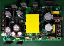
Secondary
300VDC and 6.3VDC out
1 x optocouplers EL817
1 x NE555 timer I.C.
2 x DTV56F diodes
2 x MHCHXM MBR1060F schottky diodes
1 x power FET I cannot read the type
2 x 33uF 400V electros
2 x 2200yF 16V electros
2 x 1000uF 16V electros
I have not used a LD7575 my self so it will be interesting to see how it works.
Interesting use for high voltage damper diodes!
Has anybody a spice model for a LD7575?
I shall report back when I test the device.
Ken Kranz
It has given me the opportunity to have a closer look at the design.
some details are given below;
primary side
isolated 240VAC input
1 x bridge rectifier
2 x 80uF 400V electros
1 x LD7575 I.C.
1 x SVF12N65F mosfet
across the isolation barrier
2 x optocouplers EL817
Secondary
300VDC and 6.3VDC out
1 x optocouplers EL817
1 x NE555 timer I.C.
2 x DTV56F diodes
2 x MHCHXM MBR1060F schottky diodes
1 x power FET I cannot read the type
2 x 33uF 400V electros
2 x 2200yF 16V electros
2 x 1000uF 16V electros
I have not used a LD7575 my self so it will be interesting to see how it works.
Interesting use for high voltage damper diodes!
Has anybody a spice model for a LD7575?
I shall report back when I test the device.
Ken Kranz
Attachments
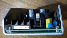
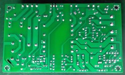
The pad side earth track from input terminal to chassis corner looks a bit lean - is there a track on the part side?
Good luck if you get keen to make a schematic.
Good luck if you get keen to make a schematic.
Well spotted, I normally have a secure earth terminal from the IEC socket to chassis so it should not be problem in my case, I have noted the LD7575 PWM controlled I.C. is on the opposite side of the PCB to the power FET it is driving, it will be interesting to run the scope over it, the track to the gate is about 7cm long it is in series with a 47 ohm gate drive resistor, the resistor is bypassed by a diode.
I have a decent isolating transformer and will use it when scoping the hot side of the cct.
I have a decent isolating transformer and will use it when scoping the hot side of the cct.
The power supply from pictures is weak because it's a flyback not a half-bridge . Max 150W but even this could be very optimistic . If is the same as the one discussed before , protection trips and issues with cold filaments and +B are to be expected ... maybe usefull for preamplifiers or simple low power single ended amplifiers .
Last edited:
Tues 1st July
First tests:
Fitted a 2.2 ohms resistor across the 6.3VDC output,
Turned on the 240VAC to the power supply.
300VDC was measured at the open circuit HV output.
5.74VDC was measured across 6.3VDC output.
Turned off and fitted a 500 ohm 200W load on the 300VDC output.
Turned on, the power supply failed to start (hiccup mode) so I turned down the output voltage pot and the device started at 260VDC output, I slowly turned the pot up to maximum and 301VDC was measured across the 500 load using a Fluke DMM, this equates to 600mA, the maximum power specified. 6.4VDC at the 6.3VDC output.
After running for 5 minutes I could only hold my finger on the flyback transformer for 10 second and the heatsink was getting hot to touch next to the switching FET. The test was stopped as the power supply will be never used at 600mA output.
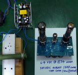
Second tests:
Two EL34s and one 12AX7 were connected to the 6.3VDC output, the cold resistance of this circuit was 0.3 ohms. A single 1000 ohm 100W resistor was used to load the 300VDC supply to 300mA. The power supply started and was left to run for 1 hour.
At start up the HV was at 301VDC, and 6.3V supply measured 6.4VDC at the base of one EL34.
At the end of the hour the HV supply had dropped 1 volt and measured 300VDC.
I could only hold my finger on the flyback transformer for about 3 seconds, the heatsink was warm not hot. After turn off when the caps were discharged I used a finger to test capacitor temperatures all were warm with the two 16V 2000uF caps the hottest.
Switching frequency 65kHz with some RF on the outputs so some additional filtering will be required.
I will only have a 200mA load on the HV and a 3.15A load on the 6.3VDC output and think it may be best if I fit a small very quiet 12V fan just to move a little air through the power supply.
At higher power levels I think the fan would need to work harder.
The 12.6VDC (4A) output was not tested under load, if I use it it will only be to run a micrcontroller PCB with relays, I find a micro uses less parts than a 555 timer.
Power supply part number : LCT250-0612300-52
BTW I had to place a small fan on the 100W resistor as it could melt solder.
I cannot find my pyrometer, it will turn up.
First tests:
Fitted a 2.2 ohms resistor across the 6.3VDC output,
Turned on the 240VAC to the power supply.
300VDC was measured at the open circuit HV output.
5.74VDC was measured across 6.3VDC output.
Turned off and fitted a 500 ohm 200W load on the 300VDC output.
Turned on, the power supply failed to start (hiccup mode) so I turned down the output voltage pot and the device started at 260VDC output, I slowly turned the pot up to maximum and 301VDC was measured across the 500 load using a Fluke DMM, this equates to 600mA, the maximum power specified. 6.4VDC at the 6.3VDC output.
After running for 5 minutes I could only hold my finger on the flyback transformer for 10 second and the heatsink was getting hot to touch next to the switching FET. The test was stopped as the power supply will be never used at 600mA output.
Second tests:
Two EL34s and one 12AX7 were connected to the 6.3VDC output, the cold resistance of this circuit was 0.3 ohms. A single 1000 ohm 100W resistor was used to load the 300VDC supply to 300mA. The power supply started and was left to run for 1 hour.
At start up the HV was at 301VDC, and 6.3V supply measured 6.4VDC at the base of one EL34.
At the end of the hour the HV supply had dropped 1 volt and measured 300VDC.
I could only hold my finger on the flyback transformer for about 3 seconds, the heatsink was warm not hot. After turn off when the caps were discharged I used a finger to test capacitor temperatures all were warm with the two 16V 2000uF caps the hottest.
Switching frequency 65kHz with some RF on the outputs so some additional filtering will be required.
I will only have a 200mA load on the HV and a 3.15A load on the 6.3VDC output and think it may be best if I fit a small very quiet 12V fan just to move a little air through the power supply.
At higher power levels I think the fan would need to work harder.
The 12.6VDC (4A) output was not tested under load, if I use it it will only be to run a micrcontroller PCB with relays, I find a micro uses less parts than a 555 timer.
Power supply part number : LCT250-0612300-52
BTW I had to place a small fan on the 100W resistor as it could melt solder.
I cannot find my pyrometer, it will turn up.
Attachments
Last edited:

Keeping such a smps module as cool as possible is always a concern, given that some just sit them in a fully enclosed box with no ventilation. At least that module pushes most of the heat dissipation to the outer metal frame, so that frame needs to be conductively heatsunk as much as practical to ambient. Often there is no thermal interface goop used for power devices, but that can be problematic, as applying a uniform and very thin smear could be nigh on impossible as the parts are soldered in already.
The transformer core should likely operate below about 70-80C surface - perhaps an IR temp gun is the easiest way to measure that.
The transformer core should likely operate below about 70-80C surface - perhaps an IR temp gun is the easiest way to measure that.
trobbins I agree with everything you have said, I had to remove the PCB to straighten the aluminium frame (see image on post #68),when I reassembled it some thermal compound was used on all all the power semiconductors on the secondary side, the input bridge rectifier and switching power FET had silpads fitted so I simply refitted them, it was tempting to leave the silpads out and use thermal paste as they are plastic encased devices (TO-220FP) maybe the double insulation is a regulation/isolation requirement.
At the moment it seems I need;
1/ a small quiet fan, many designs will run at a reduced voltage for low noise.
2/ RF filtering on the outputs.
It looks like this might work out OK for the intended application..
Note: I only tested the unit with 240VAC input and don't know how it would go with115VAC input. I have a new I.R. gun on the way it will arrive at about the same time I find my other one.
maybe a fan like this only 11dB
https://au.rs-online.com/web/p/axial-fans/4769725
Last edited:
Yeh, I've put a small 80mm PC fan in the rear of a guitar head unit that had poor ventilation and ran it on a lowish volts to allow some minor air movement - either 5V or 6.3V windings will do from a regular power supply, and regulated 6.3V may well do with a 12Vdc fan.
The RF filtering may or may not be a 'problem' requiring a solution. A more pressing issue may be to alleviate grounding related noise, given that the power supply module has a mains earth connection, and the amp will take external signal inputs with a ground, and noise may leak from the 6/12V supplies through heater-cathode interfaces or other auxiliary uses.
The RF filtering may or may not be a 'problem' requiring a solution. A more pressing issue may be to alleviate grounding related noise, given that the power supply module has a mains earth connection, and the amp will take external signal inputs with a ground, and noise may leak from the 6/12V supplies through heater-cathode interfaces or other auxiliary uses.
True re the ground problem, this amp will be for my computer, the has built in ground noise, so it will have to have a galvanically isolated audio input maybe a small transformer or a linear optocoupler design.
It is a cold morning here in Adelaide when I turned it on for an extended run with a fan to see the change in temperature from yesterdays run it went into hiccup mode, I disconnected the 6.3VDC out put and P/S started and continued to do so after reconnecting the heater load. As I don't want to modify the power supply I will draw up a small relay PCB with a PIC micro on it so I can do a controlled timed start up, this will give me control of the start up sequence and any thing else I want to control.
I use PCBway and ten 100mm x 100mm PCBs landed in Australia only cost about $50. I should be able to fit a 3 relays a PIC and a couple audio optical isolation circuits on a single PCB. I have lots of small PICs around and some small relays left over from my tube tester. I will use some of the blue relays shown here. Ken's Tube Tester
I may be able to fit a couple input transformers and a buffer on the same PCB in case the opto does not work out.
The power supply has been running for 35 minutes with the fan on and the heatsink and flyback transformer are only just warm, a good result indeed.
6.3V load 2 x EL34s and one 12AX7
300V load 1000 ohms.
Now is the winter of our discontent - but come summer and the outlook may be different ! (I jest, as I just wanted to add in some Shakespeare).
There are many ways to suppress turn-on current peaks that may lead to hiccupping. One example is to use a NTC thermistor in the heater circuit with a relay to bypass the NTC - the relay contact gets an easy time in that scenario. There are also cheap and cheerful ebay relay pcb modules with 555 timers for simple delay functions.
There are many ways to suppress turn-on current peaks that may lead to hiccupping. One example is to use a NTC thermistor in the heater circuit with a relay to bypass the NTC - the relay contact gets an easy time in that scenario. There are also cheap and cheerful ebay relay pcb modules with 555 timers for simple delay functions.
Now is the winter of our discontent .... you should see the rain in Adelaide at the moment🙂
The thermister idea is good, I was hoping to just use a current limiting resistor to pre heat the tubes a little and then short the resistor out with the relay contacts, I guess it would be easy to substitute a thermistor for the resistor.
I just had a look in my PIC box and found nine 16F18313 DIP-8 micros, RS part number 913-3734 so I must have used one at sometime, the costs amaze me
$1.42 AUD for a micro with a 10 bit ADC, and internal osc.
https://docs.rs-online.com/3025/0900766b814a945c.pdf
I could use all 8 pins by fitting three trim pots and 3 relays for a very low component count timer or maybe no trim pots and code the delay.
The power supply is still running, the flyback transformer is just above blood warm, heatsink cold to warm, the electos I'm game to touch while it is running just warm, run time now 1 hour 50 minutes.
As per your suggestion I have two of these on the way. I will still do the micro pcb.
Timer Switch JK02B 0-60 Seconds DC Adjustable Delay 12V Input Relay Module | eBay
Last edited:
I just found this thread, very interesting, because I ordered the same SMPS from Aliexpress. Fingers crossed!
The thread is interesting but,
i would like to see 500-600Volt and 250mA or thereabout. Anyone seen such a beast ?
i would like to see 500-600Volt and 250mA or thereabout. Anyone seen such a beast ?
- Home
- Amplifiers
- Tubes / Valves
- HIFI 250W Switch Power Supply DC300V@0.6A +12.6V@4A +6.3V4A