What is your freq.? If you have osc. pls check voltage ripple on input and output at 50A for me.You can put few turn more on inductor if you can, but it is OK.
I don't think you have enough capacitance on primary.330u in series is like one 165uF@400v one. If you can, replace it with bigger ones.Chas1 has 2x2200uF like you have 2x330uF, so I would like to know how much ripple do you have.
I don't think you have enough capacitance on primary.330u in series is like one 165uF@400v one. If you can, replace it with bigger ones.Chas1 has 2x2200uF like you have 2x330uF, so I would like to know how much ripple do you have.
luka said:What is your freq.? If you have osc. pls check voltage ripple on input and output at 50A for me.You can put few turn more on inductor if you can, but it is OK.
I don't think you have enough capacitance on primary.330u in series is like one 165uF@400v one. If you can, replace it with bigger ones.Chas1 has 2x2200uF like you have 2x330uF, so I would like to know how much ripple do you have.
sorry, i have 2, 330uf in parallel on each side of the doubler for 660uf each. top and bottom.
the ripple at 20 amps is 50v
at 50 amps it is really noisy i only chcked for 5 secs.
it starts getting mechanically noisy when the voltage gets to 17 volts and the pwm starts going to less than 45% on each side 90% total + 10% dead time.
the noise is like bacon frying or arc welding.
HEHE "the noise is like bacon frying or arc welding" I would imagened. Ripple at 20A is 50v I would say this is on primary side, so as I said any ripple from primary goes to secondary and there you have ripple from sec and pri, so this is heavy task for feedback to deal with.I would put in pri side as big caps as you can get/have, but first of all I would create the same feedback as for my design,with components as you need for your design.You will have to calculate them.I use Marty Brown - Power Supply Cookbook (2nd ed.)(2001), where you have everything you will need.If you don't have and you can't get this book, send me email.
sounds like a plan
i have 10 330's so i can make 1650uf on each side., or i have 8 10,000's but these are at 63 v so i would have to series then resistor balance. buut that would be a huge inrush.
i have a inrush limiter that is ntc ge type CL11 , 0.7 ohms and a max of 12 amps.
i have 10 330's so i can make 1650uf on each side., or i have 8 10,000's but these are at 63 v so i would have to series then resistor balance. buut that would be a huge inrush.
i have a inrush limiter that is ntc ge type CL11 , 0.7 ohms and a max of 12 amps.
what I would do is:
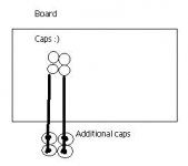
First I would add one 330 on each side for start, so that you would have 3x on each side, then go up from there. You probably can't put them on the board, so connecting them with some tick wire, as short as possible to board I think would be best.
What is your output total caps size?
First I would add one 330 on each side for start, so that you would have 3x on each side, then go up from there. You probably can't put them on the board, so connecting them with some tick wire, as short as possible to board I think would be best.
What is your output total caps size?
Attachments
it was 330uf but i stole that one for the front end,
i could use 10000uf
i have to day and tomorrow off so i am playing a lot..
thanks
i could use 10000uf
i have to day and tomorrow off so i am playing a lot..
thanks
I will try to help as much I can 😉 Put one or two 10000u on output.This should be enough.As for input, gradualy add caps.I just hope that ntc will hold.
What is your frequency?
What is your frequency?
luka thanks,
i will put a 10kuf on the output.
i can parallell ntc's i suppose.
i have browns book. n channel suggested it. it seem pretty good even i f there are some typos.
i will put a 10kuf on the output.
i can parallell ntc's i suppose.
i have browns book. n channel suggested it. it seem pretty good even i f there are some typos.
There are but if you can make something out we will help you understand.I don't think parallelling ntcs will be neccessary since is rated at 12A.I would just put in bigger one for now, let say 10-40 ohm one.But that is only if your fuse will blow.
Let me just say again that feedback will be importing thing to sort out.
Let me just say again that feedback will be importing thing to sort out.
ok
i have 1650uf on both the upper and lower.
the efficiency at 20 amps at 17 volts has come up to 82% from 50%. the noise has dissapeared but now begins to reappear around 25 amps at 17 vots so some things have been fixed.
i am going to pull off my voltage feedback and control in manualy to take out the feedback issue and play around later tonite or tomorrow.
i wonder if the proximity of the controller to the magnetics iscreating some emi?
oh well enough for today. progress!!!!!
Never parallel NTCs because they are never exactly at the same temperature neither they exhibit exactly the same resistance, and that will almost always result in one of them hogging all the current and the others staying almost cold.
Series connection of NTCs is the only approach that makes sense. Several of those 12A 0.7 ohm units in series will probably do a nice inrush supression job.
Series connection of NTCs is the only approach that makes sense. Several of those 12A 0.7 ohm units in series will probably do a nice inrush supression job.
Thats great 🙂 but I still believe that you have to much current ripple on secondary. That 10000u did help but they don't have large current ripple as do they have capacitance, so if you have some tantalium caps, I would put few of them on secondary as they can suppress a lot of ripple.If you would like to try, you can disconnect the feedback, and then you will see how much power can your supply deliver, mech. noise won't be present,... then you will be able to se how much of saggin do you get from your trafo under heavy load.
How do you test your supply at 50amps, with what load?
How do you test your supply at 50amps, with what load?
well..
the load i use is a bunch of power resistors from commercial radio transmitter surplus, ranging from 10ohms@75 watts to .175 ohms@1000 watts and a 1200watt continuos 1500watt int variac.
i am ordering some parts for a pfc and i will boost the voltage to like 400v and use the slow start for the cap charge for the doubler. i was looking at ir1150 for th pfc controller
oops,
i wound 39 turn pri/5 turns sec.
and looking over the data sheets i should have wound 18 or 19 to 1 or 2.
i used the data sheet for etd 59 ar Ae of 3.6 in stead of datasheet for e71/33/32 with Ae of 6.8.mmmmmmmmm😱
so i have too many turns, so i am going to fix this today.
i willpost some pictures when the camera gets charged, no laughing.
i was looking over the data sheet for th e71/33/32 3c90
taking the minimum voltage 270vdc from the doubler @90vac input.
n=VDCin(10^8)/f*4*Bmax*Ae
f=sw freq of transformer = 50khz
4=sq wave constant
Bmax=1000
Ae=6.82
270*10^8/(50000*4*100*6.82)=
27000000000/2046000000=19 turns
input 270vdc min
output 18vdc
Vin/Vout=15
Npri/15=Nsec=1.3 turns round up to 1.5t
this is what i did for the etd 59 i came up with 37 turns.
i want to do continuos duty and sometimes i will use this in the cold so i used Bmax 1000.
do not laugh ........unless you want to just don't tell me you are.
http://www.mcnel.com/ebaypics/DSCN1508.JPG
http://www.mcnel.com/ebaypics/DSCN1509.JPG
http://www.mcnel.com/ebaypics/DSCN1510.JPG
http://www.mcnel.com/ebaypics/DSCN1511.JPG
http://www.mcnel.com/ebaypics/DSCN1512.JPG
http://www.mcnel.com/ebaypics/DSCN1513.JPG
http://www.mcnel.com/ebaypics/DSCN1514.JPG
laugh?!! This is insane. I wish I would have resistors like that.As for pcb, well it is prototype 😉
- Status
- Not open for further replies.
- Home
- Amplifiers
- Power Supplies
- hi power smps