Two poles and zeros is what you need to have. Read my thread, take time understanding it, take my steps and you will get where you want.
About book, send me email, write aslo which two you mean
About book, send me email, write aslo which two you mean
Jim-
Well, I dunno!!!!!! 🙂
Yes, both Chryssis' and Pressman's books are excellent. Chryssis' book got me started in SMPS design, and Pressman and Brown carried the ball from there. Chryssis has two editions: 1984 &1989. Get the 1989 edition. Not sure on the info for Pressman, though I heard there was a 1991 edition.
steve,
i suppose that if the two older books built a good foundation then browns book would help with the more contemporary stuff.
but, i think for the neophyte browns book can lead you down the wrong road and to frustration 😕
😕 


i suppose that if the two older books built a good foundation then browns book would help with the more contemporary stuff.
but, i think for the neophyte browns book can lead you down the wrong road and to frustration
😕 loks like i can get pressmans book for $60 on amazon and a used chryssis bok for about $15 on amazon so... i suppose that this is what i should do TODAY!!!!!!!!!!!!!!!!
Books
Yeaaa. For $15 for Chryssis, I sure as $h1t would too! $60 for Pressman seems a bit high. Brown's book used to go for ~$40, but that price is at least five years old.
Yeaaa. For $15 for Chryssis, I sure as $h1t would too! $60 for Pressman seems a bit high. Brown's book used to go for ~$40, but that price is at least five years old.
Are there any new books like Pressman or Brown, that have been published after, let say 2002, so that they aren't old like 15 years or more?
the pressman book, is 1998 second edition hard cover, mcgraw-hill, 682 pages. from amazon. for $60-$15 dollar discount.
the chryssis book is a used one for $11.00 from amazon, but it is not here yet. supposed to be the latest edition hard cover with minimal wear and highlighting.
the chryssis book is a used one for $11.00 from amazon, but it is not here yet. supposed to be the latest edition hard cover with minimal wear and highlighting.
noise in transformer
i am playing with my power supply.
i have designed voltage feedback loops and current feed back loops which are seeming to work.
however,
when the supply is working at 80%/20% deadtime. the transformer is quiet.
when the mark/space ratio is decreased the transformer gets noisy. until is goes to 25%/75% then it gets quiet.
when operating at 80/20 and i start adjusting the current loop so the the limiter starts working it gets noisy.
or
when operating at 80/20 and i start adjusting the voltage loop so the the Error amp starts working it gets noisy.
mmmmmmm.........
drivers type
Hi SMPS Masters
I don´t have good components to build a 127VAC SMPS, 13.8VDC output, 20 Amps, but I ´ll try do it.
I have two 1000uF/250V caps, two IRF840A mosfets, one 1,5 inches outer diameter toroidal transformer, other 2 inches outer diameter tor. transf., small toroidal for to drive the mosfets, rectifier diodes, some MUR, UF, TL494 and SG3524 CIs and less schematics.
Tell me, in half bridge design, what switching frequencY is best to my toroids, how many turns for primary winding, etc., etc....
Please, help me.
Thanks now.
Re: drivers type
well,
from my still novice point of view the most important place to start is with the type of, and characteristics of the magnetic components you have available.
do you know anything about them? color, where they came from, all dimensions, material, etc
your rectifiers will have to be fast recovery to schottky.
i found that toroids are not the best for large changes of voltage ratio at high current.
I am fine tuning what i am working on, i think my construction of my prototype is causing me problems so i am making a pcb
If I have made errors in my recommendations other WILL weigh in,(which is always appreciated)

Tell me, in half bridge design, what switching frequencY is best to my toroids, how many turns for primary winding, etc., etc....
well,
from my still novice point of view the most important place to start is with the type of, and characteristics of the magnetic components you have available.
do you know anything about them? color, where they came from, all dimensions, material, etc
your rectifiers will have to be fast recovery to schottky.
i found that toroids are not the best for large changes of voltage ratio at high current.
I am fine tuning what i am working on, i think my construction of my prototype is causing me problems so i am making a pcb
If I have made errors in my recommendations other WILL weigh in,(which is always appreciated)
Ok Mr.
thanks by your fast answer. About the 1.5 inches toroid: It´s a green color ring core and 1.2cm (Ae). I don´t know the characteristics about gauss. In amidon site no there nothing. I buit it with 32 turns in 127VAC (175VDC) and it´s ok, no heat, maybe I can use 20 turns...???Yes, I have fast diodes, no problem. My SG3524 runs in 60Khz, only the a litle interference in FM reception, more in choke filters ?
Thanks
circuit boards
well i have sent the pcbs to advanced in denver for their DFM ceck and they have passed.
they seem to have the best deal for quickies at a reasonable price
any suggestions
well i have sent the pcbs to advanced in denver for their DFM ceck and they have passed.
they seem to have the best deal for quickies at a reasonable price
any suggestions
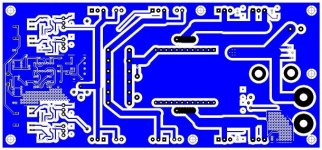
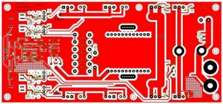
no i haven't gotten them yet. i got the feedback fairly stable. but i seem to have bad ground looks and radiated stuff running around at higher currents....so.. i thought i would put some stuff together and try it with a better layout.
and when i get them back, i am going to parallel them and run them at current each driven i think in master slave or from the same out put and sense the total power..........
we'll see how much smoke and fire i can make
and when i get them back, i am going to parallel them and run them at current each driven i think in master slave or from the same out put and sense the total power..........
we'll see how much smoke and fire i can make
sachserjuris said:Ok Mr.
thanks by your fast answer. About the 1.5 inches toroid: It´s a green color ring core and 1.2cm (Ae). I don´t know the characteristics about gauss. In amidon site no there nothing. I buit it with 32 turns in 127VAC (175VDC) and it´s ok, no heat, maybe I can use 20 turns...???Yes, I have fast diodes, no problem. My SG3524 runs in 60Khz, only the a litle interference in FM reception, more in choke filters ?
Thanks
Jimbo,
Boards look nice.
Sac,
You could try adding a potentiometer in series with your timing resistor using the following example: R(t) = 10.0kW. Replace with 9.1kW and a 2kW pot, giving you a frequency adjustability of ~ +/-10%, thus enabling you to "move" the interference off the band you're on. Just a thought.
Steve
- Status
- Not open for further replies.
- Home
- Amplifiers
- Power Supplies
- hi power smps