Ooops -- glad you reminded me! Definitely good practice to include the 10k to ground after the output caps.
Are the 24k and 39k parts proposed to replace the input bias network? Not sure there would be much of a difference between film or oxide for this use. Maybe lean toward the 24k as long as it doesn't cost too much signal from the pot. (If, for example, the top half of the gain setting isn't quite as strong as it was.)
Are the 24k and 39k parts proposed to replace the input bias network? Not sure there would be much of a difference between film or oxide for this use. Maybe lean toward the 24k as long as it doesn't cost too much signal from the pot. (If, for example, the top half of the gain setting isn't quite as strong as it was.)
Ok I'll ad the 10k resistors to ground after the output capacitors.
The 24k would go from pin 3 of the oppamp to ground. Pin 3 is input.
I will remove the temp comp circuit completely?
What pot. are you referring to?
The 24k would go from pin 3 of the oppamp to ground. Pin 3 is input.
I will remove the temp comp circuit completely?
What pot. are you referring to?
Volume pot!
It just came to me, duh!
Im going to try and implement those changes.
There's also the slightest hint if hum in the background. Not sure if its it's worth using using shielded cable for the inputs?
It just came to me, duh!
Im going to try and implement those changes.
There's also the slightest hint if hum in the background. Not sure if its it's worth using using shielded cable for the inputs?
Umm .. usually is .. 'cause inputs are often relatively high impedance.
I always do. Doesn't have to be anything special -- one of my favorites is a section of an old stereo RCA to RCA, that has one or more intermittent molded connectors. They're usually zip (like lamp cord) and so are handy for stereo, relatively small diameter, soft and flexible, and if you've been plugging and unplugging such things for long enough, there's usually a suitable one in the salvage bin.
I always do. Doesn't have to be anything special -- one of my favorites is a section of an old stereo RCA to RCA, that has one or more intermittent molded connectors. They're usually zip (like lamp cord) and so are handy for stereo, relatively small diameter, soft and flexible, and if you've been plugging and unplugging such things for long enough, there's usually a suitable one in the salvage bin.
There are many wiser folks than I on this forum when it comes to proper minimum-hum, safety-conscious techniques.
Maybe try searching 'amp input grounding for minimum hum' (on the site), or something like it.
Maybe try searching 'amp input grounding for minimum hum' (on the site), or something like it.
I was working on a note describing 'my standard practice', and had it 80% typed in, but somehow smoked it (by mistake! sorry 😱) -- and now am having trouble re-gathering my thoughts (might be the adult beverages ..).
Maybe try grounding both ends of the shield, and post whether that helps or hinders.
Maybe try grounding both ends of the shield, and post whether that helps or hinders.
Last edited:
Hey Rick,
Thanks for the responses.
I've removed the temp comp circuit.
Now to fit the resistor at the input.
I'll let you know how it works out. It may take a few days.
Thanks for the responses.
I've removed the temp comp circuit.
Now to fit the resistor at the input.
I'll let you know how it works out. It may take a few days.
I ended up using 22k inputput bias resistors instead of the 24k, grabbed the wong ones. I tried the amp like this and it sounds good. Similar to before in terms of sound. Perhaps more bass?
Also the volume control seems less sensitive to volume increase when I rotate, it does that make sense?
Also the volume control seems less sensitive to volume increase when I rotate, it does that make sense?
The decrease in volume control sensitivity is reasonable -- each wiper now has about 3x the 'load' -- 22k vs 68k (in parallel with the much lighter load of the valve grid bias resistor).
The possible bass increase is a little harder to rationalize.
How about the hum -- any improvement/change there?
The possible bass increase is a little harder to rationalize.
How about the hum -- any improvement/change there?
Last edited:
Yeah i wasn't positive about the bass increase.
The hum is about the same. Very low and in the distance.
I could def live with it. More noticeable with the closed back headphones I have. They have a stronger bass output than the grados.
So next, In the next week or so
I'm going to install the output caps and the 10k resistors on the veroboard.
Also try some shielded cable. The plan after consulting my friend is to ground one side only of the shielding.
I'm also going to try and clean up the wiring, and create a service loop as you've mentioned in the past.
I was thinking of using smaller gauge wire from the board to the volume pot. That would mean I'd have to crimp terminals on the new wire. The thinner wire would be easier to route and manage.
Let me know if you have any ideas about that.
Probably produced on the same equipment, would be my guess.
It could give a clue as to which is connected to the 'outer foil', which might be a useful tidbit if this were a low-level circuit.
Likely won't matter for this use.
It could give a clue as to which is connected to the 'outer foil', which might be a useful tidbit if this were a low-level circuit.
Likely won't matter for this use.
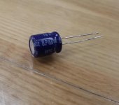
So working on putting the Bipolar caps on the veroboard. I noticed they have 2 different sized leads just like regular polarized capacitors. Any idea why that is? Should I pay attention to that?
They are the same package as polarized caps, they use the same packaging machinery...
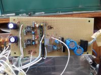
Well it's completed now. Veroboard is in and soldered up.
The shielded inputs didn't make any difference. That being said I'm happy with
How it sounds. Slight hum in the distance when no music is playing, barely noticeable.
It's been quite a journey. I think I may have even learned a thing or two.
Rick thanks for the help along the way.
The shielded inputs didn't make any difference. That being said I'm happy with
How it sounds. Slight hum in the distance when no music is playing, barely noticeable.
It's been quite a journey. I think I may have even learned a thing or two.
Rick thanks for the help along the way.
It looks mighty pretty! 😀
You're entirely welcome. Sorry again that I didn't come through for you on the input bias circuit. 😱

You're entirely welcome. Sorry again that I didn't come through for you on the input bias circuit. 😱
- Home
- Amplifiers
- Headphone Systems
- help with op amp headphone amp hum and distortion