Hi DIY's,
For decades I am reading about the great sounding LAT FET's.
There are a lot of simulations(Lineup) and builds.
I am a fan of opamp error correction and like to use it to lower distorsion and noise.
Further having about a 100Watts at hand is what I also like .
Goal:
Now comes the help I need.
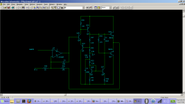
Schematic below is a combination from Elliott P101 output stage and an opamp(OPA627,LME49710,OPA1611,OPA1655).
Hopefully can someone simulate this schematic and give answers. I have tried several times last decades to use TINA and Spice without satisfying results.
Thanks Ronny.
Updated 27-2-2025


Latest version
For decades I am reading about the great sounding LAT FET's.
There are a lot of simulations(Lineup) and builds.
I am a fan of opamp error correction and like to use it to lower distorsion and noise.
Further having about a 100Watts at hand is what I also like .
Goal:
- 75...125Watt at 8ohm
- THD < 0.0001%
- Noise < -120db
- SMPS power supply
Now comes the help I need.
Schematic below is a combination from Elliott P101 output stage and an opamp(OPA627,LME49710,OPA1611,OPA1655).
- Does T1 have enough( 3x) voltage gain?
- Is the feedback(R4/C4) fase correct connected to opamp?
- Is there enough compensation to make the amp stabil?
Hopefully can someone simulate this schematic and give answers. I have tried several times last decades to use TINA and Spice without satisfying results.
Thanks Ronny.
Updated 27-2-2025
Latest version
Last edited:
Your circuit will never be stable. Your have designed a circuit with positive feedback instead of negative feedback. Your DC phasing is wrong.

Feedback still confusing. Feedback is connected to “-“ input opamp, that should be negative feedback?
Source feedback at output can be phase incorrect? . How to correct this?
I can connect feedback to “+” input but then input impedance is low.
Or can I ad capacitor in feedback loop to shift the phase?
Source feedback at output can be phase incorrect? . How to correct this?
I can connect feedback to “+” input but then input impedance is low.
Or can I ad capacitor in feedback loop to shift the phase?
Last edited:
Your MJE350 PNP adds an inversion in the loop. Also, this circuit will not work because the opamp can control up to 15v while the PNP is at 35v. You can't get there from here.Feedback still confusing. Feedback is connected to “-“ input opamp, that should be negative feedback?
Source feedback at output can be phase incorrect? . How to correct this?
I can connect feedback to “+” input but then input impedance is low.
Or can I ad capacitor in feedback loop to shift the phase?
No. All you have to do is to reconfigure opamp. Your feedback should enter the positive leg of the opamp. It’s really negated, so you’re adding a negative value, which means you’re subtracting. Unequal signs —> minus.So I need in the middle a voltage gain stage with no inversion?
So C4/R4 should be connected to pin 3?
But the driving of MJE350 is still a problem because of voltage potential differences.
Transformers cost about 10euro,s.
But the driving of MJE350 is still a problem because of voltage potential differences.
Transformers cost about 10euro,s.
You've got an inverting stage feeding back to the opamp (-) input via C25 - that looks a lot like positive feedback to me...
No, not with T1 being directly driven by an opamp with low voltage rails and a much higher potential at its emitter - looks like a recipe for a zorched OPA627, and those don't come cheap.
It needs a redesign, as there are fatal flaws that might make it blow up instantly.
Transformer version might work.
But I'm not sure.
It all depends on the transformer - what do you use?
But I'm not sure.
It all depends on the transformer - what do you use?
- Home
- Amplifiers
- Solid State
- Help, with LAT FET schematic