 Split from http://www.diyaudio.com/forums/multi-way/68301-my-morel-mtm-project-6.html#post4796981
 I have a mw144 with 30s in a transmission line. The cab is near enough the ipl M3
link: IPL M3TL mk3 Transmission Line
I think it's 8 years since I first posted, looking for help. I think I had probably been at it 8 years then. On and off.
They are OK, with a 2nd order about 2.8khz. It's nothing special though and I have taken many db away from the 30s to improve things. Leaving the tops about as loud as the bass, but a hump between 500hz and 1khz making them sing more than dance. I like dance.
Time change and so have my hobbies. It's electric bikes now. I would like to try some different crossovers though. Just not design them. Are there any designs about that are polished enough to copy with reasonable success?
Last edited by a moderator:
Well I passed through for a reason. I could feel my attention turning this way again. I may try a 3.3uf and some resistors to turn it down without effecting the x-over point. It seems the 4.3uf used here was crossing higher as resistors and coils were places across it, to the point where it was about shorted out from the sounds of things, moving the x-over beyond what the 3.3 would achieve. However.. I think I may of already done this with some electrolytic's and walked away.
I'm very interested in a very low crossover point, like 2khz.
I'm thinking a 2.5khz second order for the bass driver would roll away from a little under 1khz and then more sharply with the 1-2khz dip. Giving an effect like a higher order x-over set around 2khz. Which my 30s could work with. I have no way of modelling this though. It's at a dead end unless someone wanted to pick it up from here.
Hi Friendly1, I think my dip at 2Khz is a combination of the drivers and my baffle geometry. From talking with Terry it's not a "normal" response for the MW144's Not sure if my lot were from a batch that had this characteristic.
I've also thought about doing a lower crossover point, around 2Khz.
I found that the difference between my original 2nd order crossover at about 2.8Khz and my revised fourth order one at 2.8Khz was like chalk and cheeze. The fourth order one is MUCH better. I originally thought that this was due to the tweeter being less stressed, but I now think it may be more to do with the mw144's having their breakup better suppressed.
I'm pretty sure my measurements have quite a bit of baffle in them but I could try and subtract that to get a 2pi response which would then be ok for modeling. If I get some time I'll see what I can do 🙂
Tony.
I'm pretty sure my measurements have quite a bit of baffle in them
Tony.
Yes, I really didn't have a clue at first 🙂
I noticed someone say early on that these drivers don't really like 2nd order. A view I had to ponder for some time. I guess it's all or nothing. I think we may have a similar ear, as we both make quite extreme efforts to lower the HF performance. I'm using half a pack of resisters and 1 sheet of 2 ply kitchen roll at the moment. The 3 ply was better controlled with the window open, but though it flaps about more, the two ply has the edge sonically. I'm sure some spikes will help tighten things up.
I have used the simple x-over tools available online but that dip they talk of at 1khz will be right in the way of a 2khz design unless the full driver parameters are used. You saw the dip at 2khz though didn't you, even in free air testing? If it's position is variable, then that kind of makes using it as part of the design a bit flaky when we are literally crossing over right upon it.
I know some commercial designs have used my drivers with more than a capacitor so I guess they used the morel given figures with reasonable consistency.
Being 1 or 2khz also couldn't be more problematic with one being double the other. It's not like a couple of turns here n there will cover the tuning. I'm happy to have a go based on the morel specs though, as my drivers won't be getting measured any time soon.
I can send you a couple of sheets of this two ply if you like? lol
Richard
I must stop double posting..
The Merlin TSM used a 164mm driver and the 30 tweeter. It's x-over was 2150hz and they claimed the crossover was cryogenically treated, leading to a better sound than the esotar version they sold.
Someone posted the crossover here once, but it was a fail. Nobody could download it.
2.15khz seems a fair target for both tweeter and bass unit.
[FONT=Arial, Helvetica][/FONT]
yes definitely the Mw144's have been used with simple first order electrical filters. My very first iteration of crossover had the MW144's running full range and the tweeter with a single cap (I think 3.6uF from memory). This sounded surprisingly good, but it fell apart with "dense" music.
The other thing to consider with my own measurements is that my drivers are near enough to time aligned. with an MDT30 there will be a difference in offset compared to what I have.
I'm looking at the moment at some of the experiments I had been doing (in simulation) one that is interesting is 1.8Khz 3rd order butterworth (acoustic) slope. It's not very good at the moment though as there is a significant difference depending on the polarity of the tweeter, which indicates an issue, as it should not vary much at all with a butterworth filter.
Tony.
Arr yes. I remember now. Like for you, it's been a while. With a first order I found a nice balance and character presented itself, but only the simplest of music worked. I like very layered music with lots going on, and the individual lines just clashed like some very cheap speakers would muddle them together. Quite disastrous but the tonal quality showed real promise, or I would of given up right there.
I wonder what cryotreating would involve. I'm guessing it's the boards and inductors, but would it be done with a DC current flowing to aid how the material settled. I guess that's another thread.
Perhaps somebody knows of a commercial set of crossovers that might get me a quick crossover around 2khz. Something I might find on ebay as a starting point. I have used calc's many times and always move over to adjusting by ear soon after. I think I'm using some realistic brand multi-tapped units right now, with air cores and replacement caps. Very cheap boards that formed a good starting point. Having beefed up the tracks they are little like they started out, but I like re-purposing stuff as a cheap way of hoarding many parts.
Perhaps a minidsp (or even playing with a pc based crossover) might be a good way to experiment, but in the end to get something really good I think you will need real measurements.
I found these measurements of the MDT30 at David Ralf's site, I'm thinking that 2Khz may be a bit low for a crossover point, 4th order would probably be advisable....
Morel MDT-30 Tweeter Measurements and Modifications
I know a lot of people say go second order don't do 4th order, but my experience was that the 4th order was far superior. I went with a bessel slope rather than L/R whether that makes a difference I don't know. The thing I do know is that the phase matching on my 4th order was much better than on the 2nd so that may also play a big part.
I'll do a trace of the MDT30 SPL to get a file I can use in my sims. I'm thinking the offset is probably around 12 - 15mm in front of the MW144. (the DMS37 due to it's semi-horn loading is actually time aligned when flush mounted with the MW144's surface mounted.
Tony.
That is very good of you chap. Thank you.
I have the S version, the mdt30s. Which is likely a little different. I also feel 2khz is pushing it for 2nd order, and I find your views on the 4th order very interesting. I have always felt 2 or just above would be right. I wish the mw144 could reach a little higher as it's tonal quality is lovely, but it just can't do it. Though I will have another listen.
Thanks again
When you say offset, are you talking about their position?
Armed with a couple of fatmax tape measures, I make the dome 4mm ahead of the dust cap. I haven't recessed it yet. I don't like to be rushed 🙂
The 144's dust cap measures 4mm proud of the baffle. The HF dome about 8mm.
The 144 surprised me.
Perhaps I should get the plastic shims out.
3.8 and 6.7 (I was scared to touch it before)
2.9mm offset ?
That's a nice start 🙂
That's a lot less than I would have expected... but it is more the lowest part of the cone (ie where the voice coil attaches) that is important. That's a bit more tricky to measure, especially with tweeters... I made my estimate based on pics of the DMS37 compared to the MDT30,
Actually after going an looking at my speakers, even the coil attachment metric doesn't look like a good one as just eyballing it my tweeters would appear to be behind the MW144's I guess real measurements are the only thing that will show conclusively. I should look at my real measurements and see if I can work out just what my offet is, as if my DMS37's are very close to time aligned I think the MDT30's will have a fairly significant offset, which needs to be taken into account when modeling if not using real measurements.
Tony.
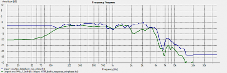
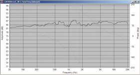
OK I have subtracted the baffle response from my measured MW144's (two not one but they measure the same just lower when done individualy).
Graph below compares my measurement to the datasheet. The main difference is my big dip at 2Khz. also the high frequencies follow the same curve but at a different level, if I adjust down the curves fit very closely.. maybe partially my mike being non calibrated.
So I think that the factory datasheet measurement with appropriate baffle effects added in will be quite ok for simulation.
Tony.
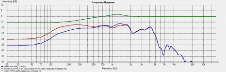
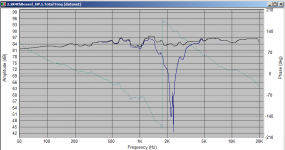
woops forgot the graph! The second one shows the actual measurement (blue) vs the curve with the baffle step curve subtracted, giving a view of how my baffle is effecting the response. Interestingly no effect at the 2Khz point....
Tony.
Tony.
Attachments
Hello Tony. Thank you for your continued interest.
I have measured the 144 again, and the dust cap attaches 10mm further back. The cap is just under 3" and iirc it's a 3" former so I think that's reliable. Making the 144's coil former attach about 6mm back from the baffles face. I'm back to rules though so some error will creep in.
Using a compass to depth gauge the tweeter, the inverted surround bottoms out 6mm back from the 3mm thick faceplate. 3mm behind the baffle.
The tweeter is 3mm ahead of the woofer still as both domes are about 10mm.
I have a router to set the tweeter flush, but have never used one. I guess it won't take long. Couple of years maybe. Unless I get building some more crossovers, so you could call them time aligned already.
That 2-3khz meander isn't expressed elsewhere is it. Could you try to measure some white noise played through some different speakers in order to see if your mic is doing this?
Last edited:
I don't think it's the mic. This measurement of my 4" SB accoustics doesn't show any dip at 2Khz. http://www.diyaudio.com/forums/full...-4-full-range-build-thread-3.html#post3483212
Tony.
Tony.
OK I've got some rough sims. I went with 12mm offset. I measured and the top of my DMS37's dome is 10mm behind the baffle. with your domes being 3mm proud of the baffle I think 12mm (which was my original estimate) is as good as anything 🙂
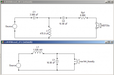
The crossovers are simple without any real attempt at smoothing out the response anomalies of the MW144. I factored in baffle step based on the TL you linked in the original post. I did two versions of the tweeter circuit, one without and one with zoble. The combined freq response is near enough to identical, but the tweeter would probably be less stressed with the zobel.
The main concern with the woofer is the hump between 1 and 2Khz (this is something I have as well and dealt with, with a notch filter). I've not put that in though.
I can provide the frd's and zma's that I've put together for your own sanity checking 🙂
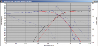
See what you think. Provided I've not made any serious mistakes I think that these would work much better than any online calculator crossovers 🙂
It's basically a 4th order acoustic Bessel at 2.2Khz.
Also I think I should probably split this off into a separate thread if that is ok 🙂
There are a few things to be wary of.
1. the mw144 datasheet states 88db sensitivity but the actual traced data is 85db (tweeter may be padded too much).
2. The low frequency response is simmed Bass reflex enclosure 20L approx 40Hz I think... shouldn't matter for the crossover.
3. I used my sealed 5L impedance for the MW144 which will be quite different to a TL, but again should probably be ok for the crossover frequency.
4. I didn't completely compensate for baffle step. I think what is there should be enough.
5. tweeter coil is 200m ohm DCR woofer coil is 300m ohm DCR (I didn't check if these are available values)
Tony.
The crossovers are simple without any real attempt at smoothing out the response anomalies of the MW144. I factored in baffle step based on the TL you linked in the original post. I did two versions of the tweeter circuit, one without and one with zoble. The combined freq response is near enough to identical, but the tweeter would probably be less stressed with the zobel.
The main concern with the woofer is the hump between 1 and 2Khz (this is something I have as well and dealt with, with a notch filter). I've not put that in though.
I can provide the frd's and zma's that I've put together for your own sanity checking 🙂
See what you think. Provided I've not made any serious mistakes I think that these would work much better than any online calculator crossovers 🙂
It's basically a 4th order acoustic Bessel at 2.2Khz.
Also I think I should probably split this off into a separate thread if that is ok 🙂
There are a few things to be wary of.
1. the mw144 datasheet states 88db sensitivity but the actual traced data is 85db (tweeter may be padded too much).
2. The low frequency response is simmed Bass reflex enclosure 20L approx 40Hz I think... shouldn't matter for the crossover.
3. I used my sealed 5L impedance for the MW144 which will be quite different to a TL, but again should probably be ok for the crossover frequency.
4. I didn't completely compensate for baffle step. I think what is there should be enough.
5. tweeter coil is 200m ohm DCR woofer coil is 300m ohm DCR (I didn't check if these are available values)
Tony.
Attachments
Last edited:
Excuse me for not following the thread from the start, maybe my suggestions can be of some help,
do some independent measurements.
1) measure/plot the physical crossover response with a resistive load and then the speaker load.
2) measure/plot the speakers without the cross overs
3) measure more than one driver
I have some Dynaudio Gemini's, (Madisound kit) they are very detailed.
Also have some Morels in 2 & 3 way setups, they are fine drivers too,
1) 15" AS woofer(3 cu ft) with MDM55,MDT30 (A bass pounder)
2) Altec Lansing 3 with 10" woofer and a new MDT32S ( A nice bookshelf unit)
Having an L-pad for the tweeter is a great option, as done in the AL3.
Something to try, a modified Gemini xover design for the MTM design? I have the schematics, not sure if I put them in ltspice, more projects for winter 🙂
I would like to try your sims in ltspice, one day, so that we can share and investigate.
Cheers & Enjoy the MTM design
Last edited:
hi rsavas 🙂 the MTM is done, but I would like to play with another crossover at some point in the future. Friendly1 is doing a TL using the mw144 and an MDT30, doesn't have measurements and needed some help. I'll probably split this off to a new thread.
I was hesitant to use my own mw144 measurements as they differ quite a lot from the datasheet (perhaps a batch problem) so I traced the datasheet measurements to do some sims.
I'll zip up all the files and attach. on the train now so probably at lunch time,
Tony.
I was hesitant to use my own mw144 measurements as they differ quite a lot from the datasheet (perhaps a batch problem) so I traced the datasheet measurements to do some sims.
I'll zip up all the files and attach. on the train now so probably at lunch time,
Tony.
That's 'pardon my french' great Tony! Thank you so much. My ear was never going to suggest a 15uf after a 3.9uf in the HF section, and it looks a piece of cake to sort out. I have some air cores for 2.5khz that can take a few more turns and I guess I can sum up the caps pretty close. I can feel myself wanting to stop typing and reach for the screwdriver with some urgency.
Rushing a little now, I believe my amp has a zobel and that my sanity would need checking if you gave me the frd's and zma's.
I should still have some good gauge enameled wire on bobbins I can offer up cores to.
00:40 and I'm getting boxes out lol
Nice one Tony! I can feel the neighbours warming towards you already 🙂
I'm putting an order together. 1mm ofc Monacor air core in the hf section, 0.6 ohm. With the correct value MKP metallised polypropylene capacitors also from Monacor. Wire would ceramic resistor is a no brainer.
The LF section has me nibbling my lip. I have cheaped out and wrote down £3.60 iron cores instead of £10 airs. I have some 16uf elcap's that are about as old as me. Little black axial things with red resin sealed ends. Alternately I'm looking at summing up 15.6uf with a 10 and 5.6 of the electrolytic type. Is this ruining a good thing? I don't imagine the iron core is an issue but do these caps that function as drains need to be metal film or something? I can't see 16uf or seem to make it. My cost right now, using the alcaps's is just £33
I have some 0.39 air cores and cores I can drop in to make the 0.47 but it seems a bit tight of me in the hf section. I likely have some big fat caps near 3.9uf but I guess matching chemistry between the 3.9 and 15 is a must.
Yes... a separate thread this has surely become. Sorry about that.
3am... Sleep wins for now 🙂
Out of interest, I'm looking at these parts at Willys HiFi, here in the UK.
- Home
- Loudspeakers
- Multi-Way
- Help with Crossover for MW144 TL