I think going with cheap parts is wise at this stage. If you get something you are really happy with you can consider upgrading to more expensive parts (but then if you are happy you probably needn't) 😉.
I bought Axon true caps for my crossover because they were good quality and cheap, I've not looked at upgrading them.
Since there are no notch filters in this, electros should be fine for experimenting (and that is what this is really). I found that electros in notch filters really didn't work very well.
Don't worry too much about it won't sound as good without better caps or coils, if the design is right it will sound far superior with cheap parts, than it will if the design is off with expensive parts.
I'll check the sim with 600m ohm on the tweeter coil, that may affect things...
Tony.
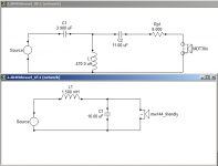
OK 600m ohm on the tweeter coil requires a bit of a tweak. I think this is better anyway 🙂 reverse null is a lot deeper, though without real world measurements it is a bit academic 😉
So basically 15uF dropped to 11uF and upped the pad resistor a bit.
Tony.
So basically 15uF dropped to 11uF and upped the pad resistor a bit.
Tony.
Attachments
Measurement files attached if anyone is feeling like checking or playing!
The MW144 and the DMS30s were spltraced from the datasheet.
MW144 had IEC baffle subtracted (though it is not clear from the datasheet whether one was used or not, I've assumed it was).
The friendly_uk_baffle_response was applied to the corrected MW144 (based on the dimentions of the cabinet linked in the first post).
A 20L BR box with tuning around 40Hz simulation was spliced in from 100 - 200 hz using frd response blender. min phase extracted and saved to MW144_TL_Baffle_corrected_min_phase.frd (which is what is used in the sim).
the MDT30s simply had minimum phase extracted and used as is.
zma for mw144 is from my 5L sealed enclosure.
zma for mdt30s traced from datasheet (and minimum phase extracted).
12mm offset used for tweeter.
No consideration of vertical lobe taken into account. MT arrangement may have a bit of an effect on this and some cabinet tilting might be necessary (not sure).
Tony.
Attachments
 hadn't realised the thread was locked, must have carried over from the original thread which I locked whilst splitting. Sorry about that!
One thing that I did with this that I'm a bit unsure of, is I boosted the level on the traced MW144 graph. The Morel spec sheet states 88db 1W/1M for the mw144, and 90db 1W/1M for the MDT30s
If you eyeball the two graphs (unfortunately poor quality) the MW144 one definitely seems off, whereas the MDT30s one looks pretty spot on.
My Own MW144's pair with a DMS37 seem to be at the right relative level to indicate that if the DMS37 is 93db as per spec then the MW144s would be 88db, so I think it is probably reasonable to have adjusted it.
Just in case it shouldn't have been a revised tweeter network is also attached which will work with a mid 3db lower.
Tony.
Attachments
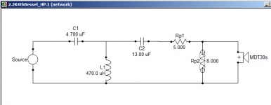
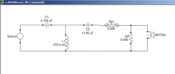
I just pulled out my 'by ear' crossovers. I actually used the same 1.5mH low pass inductor, but with an even larger 22uf cap than the 16uf I'm about to try. That was quite a surprise. My high pass revolves around a smaller 3.3uf cap with a 0.43mH coil not a 0.47 but it's really not that dissimilar looking
Pulling out more spaghetti from behind the tweeter, I quietened it down with 4.7ohms on the way, Then put 13.6 across it to probably give a similar volume reduction with a smaller resistance increase. Looking at second order designs like mine, a 3.3 targets 2.5khz as a 3.9 does in a bessel 3rd order. My coil is tiny though. Just as the low pass cap is big.
I'm surprised how close these are. I will have to laugh if it sounds no different 🙂 Though the calcs I'm using get nowhere near the figures you have provided. So it will surely be a change.
Thanks for your continued help Tony.
Hope the couple of bits I was missing arrive soon. My irons running out of gas
Last edited:
I look forward to the outcome. In the end if you can do your own measurements it will enable you to get the best results. There are quite a few assumptions when modeling with factory data 🙂
The LPAD of 3.9 and 13.6 probably indicates that the 88db adjusted measurement is fine, so the revised tweeter network is probably not necessary.
attached is sim with your original values. I'm surprised it is as close to 2.5khz as it is, if you used standard calcs!
I'll add in some targets but I suspect it is nowhere near 2nd order acoustic 😉
Tony.
Attachments
I used standard calcs to avoid going to low for the HF unit, and to be sure any secondary components didn't just short out what came though the primary one's. Then I went by ear and ended up with the above. I never tried 3rd order though as my spare's bag isn't endless. Consisting mostly of old kef based speaker x-overs and magnet wire.
I always wanted to go higher with the 144 as I like it's tone, but it just won't work. Bringing the HF unit right down towards 2khz seems to make that area lack weight, but I'm starting to think that could be all in the mind. That I may actually want something imperfect, though I'm building something else. There was always something missing about that point, and your your kindly done model shows.. yes there was.
Today I put the new trial LF section in and put a single (and very large) 2.2uf on the HF unit keeping the resistors in place. That something missing is now like a huge rift has opened up, yet somehow the 144 does sound better swapping the 22uf electrolytic for a better 16uf cap, and this big 2.2 really beats the electrolytic 3.3 and iron inductor hands down. I can't wait to lower the x-over point again with a better filter, and see how your other magic works.
I think this is where I got to before, but while I was heading in the right direction, I was forced into using poor parts. So I lost my way. All my parts for trials are used you see. Even now some bits going in must be 40yo. I have really pushed the boat out spending £3.95 on a capacitor lol
As ever, It's all good fun! 🙂
Hmm when I said electros should be fine I was thinking new ones LOL! 😀
There are definitely advantages to going with film caps, and I would recommend getting some when you are happy with things. I have not put any ESR into the sims, so you won't get any peaking problems changing to film caps (which is the main gotcha if a design has factored in Electro ESR) 2.2 on the tweeter is definitely going to leave a BIG hole going the other way with a 4.7uF should be better.
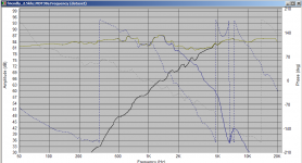
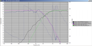
I've attached the sim again with target acoustic 2nd order L/R at 2.5KHz in red. This should give a good indication as to why the online calculators don't give you want you want. The drivers response should be following the red lines as closely as possible (if you want a 2nd order acoustic crossover).
2nd attachment compares your filter with a 2.2uF cap, 3.3uF cap and 4.7uF cap. The reverse null is with the 4.7uF .
Finally a third attachment to show what the filter is really doing (sort of ) with respect to accoustic targets.
What you have is close to a 4th order LR at 2.1Khz on the low pass, and (at least to the crossover point) a 4th order bessel at 2.5Khz on the tweeter. 🙂
I hope this illustrates the difference between a theoretical filter, and how it behaves when combined with a drivers impedance and FR! edit: actually that 4th order match on the HP is with the 4.7uF with the 3.3 it is closest to 4th order bessel at 3.1Khz! 😉
Are you getting the bug to do sims yet? 😉 with real measurements it is even better!!
Tony.
There are definitely advantages to going with film caps, and I would recommend getting some when you are happy with things. I have not put any ESR into the sims, so you won't get any peaking problems changing to film caps (which is the main gotcha if a design has factored in Electro ESR) 2.2 on the tweeter is definitely going to leave a BIG hole going the other way with a 4.7uF should be better.
I've attached the sim again with target acoustic 2nd order L/R at 2.5KHz in red. This should give a good indication as to why the online calculators don't give you want you want. The drivers response should be following the red lines as closely as possible (if you want a 2nd order acoustic crossover).
2nd attachment compares your filter with a 2.2uF cap, 3.3uF cap and 4.7uF cap. The reverse null is with the 4.7uF .
Finally a third attachment to show what the filter is really doing (sort of ) with respect to accoustic targets.
What you have is close to a 4th order LR at 2.1Khz on the low pass, and (at least to the crossover point) a 4th order bessel at 2.5Khz on the tweeter. 🙂
I hope this illustrates the difference between a theoretical filter, and how it behaves when combined with a drivers impedance and FR! edit: actually that 4th order match on the HP is with the 4.7uF with the 3.3 it is closest to 4th order bessel at 3.1Khz! 😉
Are you getting the bug to do sims yet? 😉 with real measurements it is even better!!
Tony.
Attachments
Last edited:
Sorry for the disappearing act. I got a short holiday while the weather was good (Southend on sea) And didn't want to announce the house would be empty.
I got back and got my prototype together, and what can I say. Disastrous. It sounds totally different. Even some of the lyrics sound off. Instead of "Then I saw her face, now I'm going to leave her" it sounds more like "I'm a believer"
I will report back tomorrow 🙂
I got back and got my prototype together, and what can I say. Disastrous. It sounds totally different. Even some of the lyrics sound off. Instead of "Then I saw her face, now I'm going to leave her" it sounds more like "I'm a believer"
I will report back tomorrow 🙂
Hi Friendly1 I assume the song you were talking about was The Monkey's "I'm a believer", and I also assumed your comment was a joke 🙂 If it wasn't then, I would say that even if you didn't think it was an improvement, then if you are hearing the lyrics correctly now then it probably was 😀
Hope you didn't take my LOL the wrong way!
Tony.
Hope you didn't take my LOL the wrong way!
Tony.
Oh yes, A joke indeed! Sorry my continued tardiness makes it look like I spat my dummy out. That was not my intention. Your a gent Tony.
I'm starting to think I don't like the sound of the tweeter towards it's lower end. I just keep wanting to turn it down. At first by 1.9db as I had the 1.6ohm and 33ohm to form an L-pad. But still found my hand placed ahead of the tweeter so there was no line of sight to my ears, sounded more in prospective. Then I fitted different values, a 4.7 in series and 6.8 in parallel. It's just what I had but figured at 2.5khz the tweeter exhibits 7ohms and then the resistors do look a better pairing. However this level of attenuation make me check it was still working 🙂 I think you put an L-pad in one drawing using a 5 and 8 iirc and switched the capacitor from 3.9 to 4.7 and this cap switch has me scratching my head a little. Your L-pad has raised the tweeter load the x-over see's by an ohm, so I expected a smaller capacitor not a bigger one. I'm still looking at all this now. I might actually move the hf x-over up a bit to loose some of the overlap where both transducers are at work, as it seems almost compressed hearing both. Of which I much prefer the mid/bass driver.
I wanted to post when I had a more solid opinion, but I'm looking at an L-pad purchase I think. Then I can paint a better picture.
Thank you for your continued interest. Perhaps you know of a free program I can use with a mic to get some graphs of what's happening?
Assuming you are running windows this is what I would recommend HOLM Acoustics
and http://www.diyaudio.com/forums/software-tools/145662-holmimpulse-measurements-practice.html
One thing to be aware of. Correct, doesn't normally sound good when you are used to hearing something incorrect. Listening for a time will the best way to determine if you are just not used to the new sound, or if there is something wrong with it.
Something Earl Geddes said to me a while back was that just because it sounds better doesn't mean it is right. I took it to heart and decided to persevere with what seemed correct (from measurements and sims) rather than what sounded "right" to me, and after a while found I preferred the "correct" sound.
BUT we are dealing with sims from manufacturers curves here so it is quite possible something is NOT correct. Getting real measurements is the best way forward.
Now the other thing to consider here is that I DID adjust the overall level of the woofer up a few db (I think maybe three db??) due to there being some discrepancies between the stated efficiency of the MW-144's (and my own relative measurements agreeing with the 88db datasheet spec) and the level on the graph which appeared to be around 85db. So it may be possible that the sim is in fact making the tweeters 1 - 3 db higher than they should be.
Just using an lpad to bring it down another couple of db won't necessarily give ideal results.
Getting some relative level measurements between the woofer and tweeter would be a good starting point 🙂
Tony.
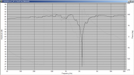
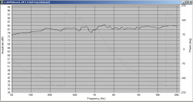
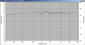
The other thing that may now be more prominent is the hump between about 1100 and 1400Hz. This may be what you are thinking is not liking the low end of the tweeter.
This can be dealt with using a notch filter, but I didn't want to go that far without real measurements.
The graph below shows it. I have a notch in my own crossover to deal with a similar response anomaly, however it changes the whole low pass filter when adding the notch.
Tony.
This can be dealt with using a notch filter, but I didn't want to go that far without real measurements.
The graph below shows it. I have a notch in my own crossover to deal with a similar response anomaly, however it changes the whole low pass filter when adding the notch.
Tony.
Attachments

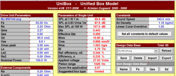
Morel MW 144 specs from Madisound needed to calculate efficiency and SPL.
Re=5,2
fs =52 Hz
Qes =0.71
Vas =8.0 ltrs
Sensitivity 1W / 1m 88 dB
no=9,78*10^(-10)*Vas*Fs^(3)/Qes=0,001549
SPL(1W/1m)=112,2+10*log(no)=84,1 dB
SPL(2,83V/1m)=SPL(1W/1m)+10*log(8/Re)=86 dB
The published value of 88 dB/1W/1m appears to not be in order.
Re=5,2
fs =52 Hz
Qes =0.71
Vas =8.0 ltrs
Sensitivity 1W / 1m 88 dB
no=9,78*10^(-10)*Vas*Fs^(3)/Qes=0,001549
SPL(1W/1m)=112,2+10*log(no)=84,1 dB
SPL(2,83V/1m)=SPL(1W/1m)+10*log(8/Re)=86 dB
The published value of 88 dB/1W/1m appears to not be in order.
Thanks Lojzek, I didn't even think about checking (I didn't know the formulas but unibox calculates efficiency).
The average params that I measured for my own MW144's are below.
Not quite as low as the datasheet but still less than the stated 88db Seems like someone stuffed up there (and me too for using the wrong figures).
I'll have to adjust (though some real measurements would definitely be best). I think I'll go with the actual level from the trace which seemed to be around 85db). My own drivers calculate at almost 86db 1W/1M so there may be some variability.
Tony.
Attachments
Last edited:
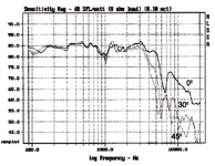
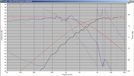
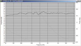
OK I've re-done the MW144 frd from scratch, as I was uncertain after all the stuff I've done whether I could trust the original. First attachment is what the response looks like with the original post 22 crossover. Obviously too hot in the high frequency range with the revised frd.
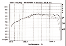
2nd post is what the response would look like with the revised tweeter crossover in post 25 (which I posted in case the 3db too hot version was not right). This is possibly still a little hot.
3rd pic is with more attenuation (using the tweeter net in the 4th attachment).
I've also attached the revised MW144.frd baffle corrected and a BR low frequency response blended in for below 100Hz.
Tony.
Attachments

Last edited:
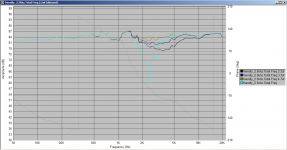
I thought I'd also show the difference between the tweeter network above and the orig one in post 22 with an 8 ohms in parallel with the tweeter. The adjustment to the caps was to bring up the slight depression between 2 and 5Khz.
It may be worth trying with the original tweeter net with just the added 8 ohm resistor though as the difference isn't huge. The original + 8 ohms parallel is the blue curve. Black is the network in the post above.
Tony.
It may be worth trying with the original tweeter net with just the added 8 ohm resistor though as the difference isn't huge. The original + 8 ohms parallel is the blue curve. Black is the network in the post above.
Tony.
Attachments
Last edited:
I ordered the L-pad today. I'm going to use it to ballpark the tweeters level. Than try and make a crossover that relies on a little attenuation in the form of an L-pad, so that I can still adjust the level up and down a little to account for mistakes that will likely creep in. My second capacitor (a 12uf) for instance is an old elcap black electrolytic. The axial ones with red resin. Known for high resistance. The 16uf in the low pass is also one. Plus I don't know the inductor resistances in my mock up. When I get close to happy, I would like to post them all, along with the actual values of what I'm buying, so that you might once more run the numbers for me. It's all pretty fudged right now. I'm not sure I will get to try a 4.7uf as the first part of the hf section as the supporting components might be a struggle. I think the 3.9 will produce the results though. I will see next week when the L-pad gets here (he says, with a big smile on his face)
It's 4:20am so I will comb back through whats been talked about tomorrow. Thank you.
Richard
It's 4:20am so I will comb back through whats been talked about tomorrow. Thank you.
Richard
- Home
- Loudspeakers
- Multi-Way
- Help with Crossover for MW144 TL