Hi, I am hoping someone can help me with this amp, I have spent a lot of time looking for the problem.
-I started this project and when I needed to buy the mosfot, (Hitachi 2SJ50, 2SK135). I found they were off sale. Then I found that Profusion sold replacement models, (ECF10N20 and ECF10P20), I bought them and mounted them but at the output it had a noise as if it was AC. And that is that it was oscillating. The oscilloscope shows a frequency of 8-9Mhz, with nothing at the input.
-I have been reading in this forum that these mosfets have been mounted as Hitachi and other replacements, and I have seen that the schematic may need some modification, like adding some capacitor or changing some resistor. But my knowledge does not reach this.
- With help, I changed the capacitors C6 and C7, from 33pf to 180pf, but it was not enough, the AC noise at the output is attenuated, but it is still oscillating and it is impossible to regulate the Offset.
-This is why I am asking if someone can help me to get it to work with these Exicon mosfets, because with Hitachi mosfets this schematic work well.
Also, I am looking on this website for alternatives in case I don't find a solution to my project, and use part of the main components, such as Mosfets and power supply.Only I found this proyect with ECF10N20 & 10P20 mosfet mounted. https://www.diyaudio.com/community/threads/elektor-axl-v2-with-lateral-mosfets.332535/
But I don't know if this project could work with double pair of mosfet and power supply could be 50V.
Thank you so much.
Attachments
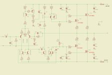
This one looks like yours, is simpler and works no prob with Hitachis and Exicons. If you pair Q1 and Q2 well, offset will be low.


I found a few older threads here mostly regarding older parts, and some stability solutions which do not yield good results with parts now available. So I figured we could have a thread dedicated to using the Exicon mosfets in novel ways I have not seen mentioned here.
Like most people, I encountered oscillation when using multiple devices, and tried the usual higher gate resistor values, and capacitors. By the time these measures could help, the amp was too slow, which in turn caused feedback loop stability issues. So, I did some research and found that that the culprit is loop currents...
Like most people, I encountered oscillation when using multiple devices, and tried the usual higher gate resistor values, and capacitors. By the time these measures could help, the amp was too slow, which in turn caused feedback loop stability issues. So, I did some research and found that that the culprit is loop currents...
- Transistorlegacy
- Replies: 28
- Forum: Parts
Hi there,I've got an amp with these Exicon mosfets running and redoing it now again from scratch,as I did some modifications and resoldering a few times didn't do any good to the platines...I would like to give you some help here,try it out if you want.The feedback arm can be reduced and kept as low as poss consitent with a reasonable high input impedance,so that the base current mismatch caused by beta variations will give a minimal dc offset.A low value for R11 also gives a low value for R1 and 1B and R12: R11=11K; R1=11K; R1B gets put on the Base of T1(after R1) and C4 change to 220uF.The value of C4 gives a LF-roll-off with R12 (-3dB @1,5Hz) to prevent a LF rise in distortion due to capacity non linearity.If R 12 is reduced to minimize the source restistance ,seen by T2,then the value of R11 is sealed(related to) to preserve the same closed-loop gain, and reduces the voltage drops caused by input transistor base current.
R25-R28 I would make them a little higher to 0.22 Ohm minimum 5W. A small 270 pF Polyester should go on the base of the T8/9 couple toward R18(collector).this whole line from the collectrors T8/9 towards the 0.22 Ohm resistors on the finals could be shielded .A ferrid bead (Wuerth 74279224551) could be put on the gates of each finals to further reduce oscillating.R 21-24 should then be reduced to about 100 Ohms.If the input transistors are matched and the Resistors R5/6 are made 0.1% precision then maybe the trimmer is not even needed...Good luck and good work! Cheers Frank
R25-R28 I would make them a little higher to 0.22 Ohm minimum 5W. A small 270 pF Polyester should go on the base of the T8/9 couple toward R18(collector).this whole line from the collectrors T8/9 towards the 0.22 Ohm resistors on the finals could be shielded .A ferrid bead (Wuerth 74279224551) could be put on the gates of each finals to further reduce oscillating.R 21-24 should then be reduced to about 100 Ohms.If the input transistors are matched and the Resistors R5/6 are made 0.1% precision then maybe the trimmer is not even needed...Good luck and good work! Cheers Frank
@jacques antoine I would at least use a CCS above Q1 and Q2 to improve linearity on that circuit. I've built a few of those Hitachi lateral fet output amps and they sound very good. I tend to favor the j50 / k135 outputs rather than the lower voltage j49 / k134. If you can find a few pairs of j56 / k176, you can get 200W + depending on current available from Q3 and Q5. Two pairs shouldn't be an issue but bandwidth may not be as good due to the increased gate capacitance.
Use 560R (P) and 680R (N) gate stoppers and a zobel across D-G of the Exicons (220R + 22pF).
@jacques antoine The CCS will improve PSRR due to power supply rail sag. That can modulate the input signal, affecting IMD as well. Being the rails aren't as high as more powerful amps needing to reduce the rails due to Q1/Q2 limits. Even some LM317/337 regs divorcing main B+/B- from the input diff pairs should help somewhat.
Reducing the 62k input diff pair load and running RC filters with zeners from main rails would IMO help in a few areas and should noticeably improve overall performance.
Reducing the 62k input diff pair load and running RC filters with zeners from main rails would IMO help in a few areas and should noticeably improve overall performance.
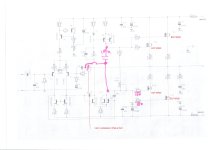
Thank you very much, but there is something I don't understand, I show you in the picture.You may try these mods
Attachments

got it. Re-rooting the compensating capacitor.
Step1: Disconnect from the power output (double slash).
Step2: Connect o the VAS driver output instead (new wire).
Step1: Disconnect from the power output (double slash).
Step2: Connect o the VAS driver output instead (new wire).
Last edited:
Great article, but I understand that it mainly it refere to plastic Exicon lateral, I don´t know if it work with ECF TO3 too. ThanksI found a few older threads here mostly regarding older parts, and some stability solutions which do not yield good results with parts now available. So I figured we could have a thread dedicated to using the Exicon mosfets in novel ways I have not seen mentioned here.
Like most people, I encountered oscillation when using multiple devices, and tried the usual higher gate resistor values, and capacitors. By the time these measures could help, the amp was too slow, which in turn caused feedback loop stability issues. So, I did some research and found that that the culprit is loop currents...
- Transistorlegacy
- Replies: 28
- Forum: Parts
@bucks bunny, In the photo I mark with a red circle I don't understand, what if this wire is cut?
Attachments
I'll give it a try, thanksHi there,I've got an amp with these Exicon mosfets running and redoing it now again from scratch,as I did some modifications and resoldering a few times didn't do any good to the platines...I would like to give you some help here,try it out if you want.The feedback arm can be reduced and kept as low as poss consitent with a reasonable high input impedance,so that the base current mismatch caused by beta variations will give a minimal dc offset.A low value for R11 also gives a low value for R1 and 1B and R12: R11=11K; R1=11K; R1B gets put on the Base of T1(after R1) and C4 change to 220uF.The value of C4 gives a LF-roll-off with R12 (-3dB @1,5Hz) to prevent a LF rise in distortion due to capacity non linearity.If R 12 is reduced to minimize the source restistance ,seen by T2,then the value of R11 is sealed(related to) to preserve the same closed-loop gain, and reduces the voltage drops caused by input transistor base current.
R25-R28 I would make them a little higher to 0.22 Ohm minimum 5W. A small 270 pF Polyester should go on the base of the T8/9 couple toward R18(collector).this whole line from the collectrors T8/9 towards the 0.22 Ohm resistors on the finals could be shielded .A ferrid bead (Wuerth 74279224551) could be put on the gates of each finals to further reduce oscillating.R 21-24 should then be reduced to about 100 Ohms.If the input transistors are matched and the Resistors R5/6 are made 0.1% precision then maybe the trimmer is not even needed...Good luck and good work! Cheers Frank
Great, I'll do it.Use 560R (P) and 680R (N) gate stoppers and a zobel across D-G of the Exicons (220R + 22pF).
Answered @ #12@bucks bunny, In the photo I mark with a red circle I don't understand, what if this wire is cut?
I understand that the scheme would be as followsgot it. Re-rooting the compensating capacitor.
Step1: Disconnect from the power output (double slash).
Step2: Connect o the VAS driver output instead (new wire).
Attachments

- Home
- Amplifiers
- Solid State
- Help with an oscillating amplifier with Exicon mosFET ECF10P20 & ECF10N20