Uhm...
Fixed it?
I first thought: Well this 12AQ5 is basically useless. Let's run it at 330V. And it didn't do anything special; same old low gain and low current draw.
I then told myself: How about the 6AQ5s? Can I run them at 330V? Let's try it! Oh whoops. The one with the small plate red-plates. Let's take that one out of the circuit. Woah. It sounds great now.
Moral of the story: My 12AQ5 and one of my 6AQ5s are "faulty". The 6AQ5 draws current, but it does almost no amplification and it even messes up the other tube. Removing it made the other 6AQ5 work pretty well. From what I had heard from the PCL805 as the output tube at 4W, I could say this produces 5W or so. The "5W" is purely subjective and it may be lower or higher but I "guess" that it's around 5W RMS or so at 3Ohm.
The good 6AQ5 red-plates at 330V when idling, but it quickly goes away when I set the input volume at max (2V P-P).
It doesn't red-plate with the original 170V.
The 330V and the 170V don't make much difference in terms of amplification, but it does improve the distortion at max volume.
Decreasing the cathode resistor from 48Ohm to 24Ohm does not do anything.
The 12AQ5 doesn't red-plate at any voltage!
I will test the other 6AQ5 which I think might be faulty, with it's own separate cathode resistor to see if it'll help the amplifier or it just does it's stupid thing again.
Last edited:
Oh man it's awesome 😀
I've hooked up my Sennheiser HD58X Jubilee (150Ohm) to it with the channels in parallel and it sounds great with that one 6AQ5.
I tried the separate cathode for the "faulty" 6AQ5 and it still behaves strangely. Not only it reduces the amplitude, it also reduces the ratio of the low frequencies to the high frequencies and it sounds muffled.
I still have to test it with a separate input capacitor with a grid leakage resistor to see if that helps.
Oh man it's awesome 😀
I've hooked up my Sennheiser HD58X Jubilee (150Ohm) to it with the channels in parallel and it sounds great with that one 6AQ5.
I tried the separate cathode for the "faulty" 6AQ5 and it still behaves strangely. Not only it reduces the amplitude, it also reduces the ratio of the low frequencies to the high frequencies and it sounds muffled.
I still have to test it with a separate input capacitor with a grid leakage resistor to see if that helps.
Thanks for the update, AbaddonD.
It is amazing how “bad valves” get in the way of progress. The use of the “unused pentode” in the PCL805 as a cathode follower has not changed the gain of the first stage, but has substantially reduced its output impedance, making it “stronger” to drive the following AQ5's … with such low bias, potentially into the positive grid region … which the 'naked' first stage could not do.
If you have a 5 W resistor around 10 kΩ or so, feel free to substitute that in for R₇.
Actually, ALL of these would work, safely (and lower values are definitely preferred):
4.7 kΩ, 5 watt
6.8 kΩ, 4 watt
8.6 kΩ, 3 watt
10 kΩ, 2 watt
15 kΩ, 1½ watt
22 kΩ, 1 watt
33 kΩ, ¾ watt
47 kΩ, ½ watt
Again, lower Ω is better … at least up to the point where one is getting “too close” to the PCL805's pentode's max-plate dissipation limit!
Thanks again for being so enthusiastic.
Respectfully,
-= GoatGuy ✓ =-
PS … you might now consider taking TP measurements again.
... With it in its “awesome” configuration.
This time… let's multiply by 11× instead of 10×, since 1000 kΩ to 100 kΩ divider is a 11 to 1 thing. If you measure all test points (including B+), well … we'll have a new basis for analysis that'll be more accurate.
Best wishes,
-= GG =-
PS... and please go purchase a cheap (less than $10!) multimeter! You'll love it, until you get a second one. The first will 'become the second', and you'll be surprised how often having two multimeters is handy. Wish - wish - wish - wish.
Last edited:
Thanks for the update, AbaddonD.
It is amazing how “bad valves” get in the way of progress. The use of the “unused pentode” in the PCL805 as a cathode follower has not changed the gain of the first stage, but has substantially reduced its output impedance, making it “stronger” to drive the following AQ5's … with such low bias, potentially into the positive grid region … which the 'naked' first stage could not do.
If you have a 5 W resistor around 10 kΩ or so, feel free to substitute that in for R₇.
Actually, ALL of these would work, safely (and lower values are definitely preferred):
4.7 kΩ, 5 watt
6.8 kΩ, 4 watt
8.6 kΩ, 3 watt
10 kΩ, 2 watt
15 kΩ, 1½ watt
22 kΩ, 1 watt
33 kΩ, ¾ watt
47 kΩ, ½ watt
Again, lower Ω is better … at least up to the point where one is getting “too close” to the PCL805's pentode's max-plate dissipation limit!
Thanks again for being so enthusiastic.
Respectfully,
-= GoatGuy ✓ =-
Yeah, one bad tube and it can ruin EVERYTHING; also waste your time xD
I should have a high wattage resistor around 2K or so somewhere. I will find one and substitute it.
About the multimeter, isn't it worth waiting a bit to get the GW Instek GDM 450A? It's a 19999 count meter for $30! It'll take about 1 month to be able to buy it. I was thinking about buying a 6L6GC listed for less than $10. It "looks" clean. It would still take 1 month to that meter even if I save up the money for the 6L6GC.
Thanks for all your help man. I couldn't have done it without you!
Also, a big thanks goes to the people who suggested a few stuff regarding the problems.
PS … you might now consider taking TP measurements again.
... With it in its “awesome” configuration.
This time… let's multiply by 11× instead of 10×, since 1000 kΩ to 100 kΩ divider is a 11 to 1 thing. If you measure all test points (including B+), well … we'll have a new basis for analysis that'll be more accurate.
Best wishes,
-= GG =-
PS... and please go purchase a cheap (less than $10!) multimeter! You'll love it, until you get a second one. The first will 'become the second', and you'll be surprised how often having two multimeters is handy. Wish - wish - wish - wish.
I will measure the voltages and mention them in about an hour.
Oh… very important … regarding the RED PLATE thing.
First it is really dangerous to just double the B+ of an amplifier. If the values of the resistors power tolerance can't take it … things blow.
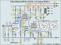
Second, if you want to have the much higher B++ supply, see the attached diagram. I've specially marked the values that need changing.
Anyway, hope it goes well.
-= GG =-
First it is really dangerous to just double the B+ of an amplifier. If the values of the resistors power tolerance can't take it … things blow.
Second, if you want to have the much higher B++ supply, see the attached diagram. I've specially marked the values that need changing.
Anyway, hope it goes well.
-= GG =-
Attachments
About the multimeter, isn't it worth waiting a bit to get the GW Instek GDM 450A? It's a 19999 count meter for $30!
… NO … it is not worth waiting.
You continue to be impressed by lots-of-precision, when it is absolutely not required.
Seriously!
Remember, in the “good old days” like the peak of the 1970s, really, really well-respected engineers were using so-called "VTVM¹" analog meters to do their measurements. These rarely could deliver better than ½% precision. Your basic $7.95 3½ digit el-cheapo pocket meter delivers the same ½% precision.
Now … off with ye to a retail store, and go buy an el-cheapo, but decent meter, man!
Just Saying,
-= GoatGuy ✓ =-
________________________________________
¹ VTVM → vacuum tube volt meter. Had 10 MΩ input. Beautiful precision (½%) meter movement. Works of art.
Last edited:
Oh… very important … regarding the RED PLATE thing.
First it is really dangerous to just double the B+ of an amplifier. If the values of the resistors power tolerance can't take it … things blow.
Second, if you want to have the much higher B++ supply, see the attached diagram. I've specially marked the values that need changing.
Anyway, hope it goes well.
-= GG =-
I was just testing it. I will never keep tubes that hot. And yes, the resistors can catch on fire just like when one of my 48Ohm resistors was shorted across the B+ 😀
My power supply can deliver over an amp BTW xD
I might put the 48Ohm resistors in series if I ever want to run it off 320-330V.
About the diagram; why does the value of C4 need to be dropped?
I was just testing it. I might put the 48Ohm resistors in series if I ever want to run it off 320–330V.
About the diagram; why does the value of C4 need to be dropped?
Technically C₄ doesn't need 'dropping' to 220 µF from your 820 µF, per se. However, if you look carefully, I've included a separate R and C for each output valve running 'in parallel'.
By doing this (ironically), you actually could put ALL the AQ5's that you own in the circuit at the same time, and to whatever level of contribution each has the potential to make, they'd all fairly add their part to the output.
But it requires separate R and C in the cathode. Just like it requires separate grid resistors. And separate screen-to-high-volt resistors. The ONLY terminals of parallel tubes that are hooked directly together are the anodes.
Yours,
-= GoatGuy ✓ =-
Yeah, precision in here is unnecessary.… NO … it is not worth waiting.
You continue to be impressed by lots-of-precision, when it is absolutely not required.
Seriously!
Remember, in the “good old days” like the peak of the 1970s, really, really well-respected engineers were using so-called "VTVM¹" analog meters to do their measurements. These rarely could deliver better than ½% precision. Your basic $7.95 3½ digit el-cheapo pocket meter delivers the same ½% precision.
Now … off with ye to a retail store, and go buy an el-cheapo, but decent meter, man!
Just Saying,
-= GoatGuy ✓ =-
________________________________________
¹ VTVM → vacuum tube volt meter. Had 10 MΩ input. Beautiful precision (½%) meter movement. Works of art.
I have had lots of multimeters in the past. Maybe over 7. Since they have almost no protection, they've all died.
One of them got blasted with over 3KV. Hilarious.
I will get a sub $10 multimeter in about 20 days. I think the Victor ones are "OK".
Oh one more thing. I will be getting an Ahuja HRC-32T tube amplifier. It has three ECC83s and 2 EL84s in push-pull I think. It'll be a birthday gift 😀
Already excited to own a real tube amplifier. I might test the audio transformer with my own amplifier and see how it goes.
The weird thing is that I can't find any information on it! Just one forum with someone recommending it.
Technically C₄ doesn't need 'dropping' to 220 µF from your 820 µF, per se. However, if you look carefully, I've included a separate R and C for each output valve running 'in parallel'.
By doing this (ironically), you actually could put ALL the AQ5's that you own in the circuit at the same time, and to whatever level of contribution each has the potential to make, they'd all fairly add their part to the output.
But it requires separate R and C in the cathode. Just like it requires separate grid resistors. And separate screen-to-high-volt resistors. The ONLY terminals of parallel tubes that are hooked directly together are the anodes.
Yours,
-= GoatGuy ✓ =-
Yes, I noticed the separate R and C pairs for each tube.
I don't think I'll be doing that. Too much work for too little "gain" (pun intended) 🙂
I'm currently measuring the voltage of the test points.
Should I measure every one of them?
Yes, I noticed the separate R and C pairs for each tube.
I don't think I'll be doing that. Too much work for too little "gain" (pun intended) 🙂
Well … if you wanted to follow up on your original idea (of using 3 valves in parallel on the output to substantially increase output power), this new diagram is definitely the way to do it. Indeed … you could easily drive up to 8 of the valves by replicating this to as many sockets and 12AQ5's (6AQ5's) as you obtain.
I'm currently measuring the voltage of the test points.
Should I measure every one of them?
YES. Paper, pencil, measure them all quickly. Then this time multiply by 11. Including B+.
B+: 164.2V
TP1: 1.73V
TP2: 100.1V
TP3: 91.5V
TP4: 163.1V
TP5: 162.0V
TP8: 162.7V
TP9: 3.4V (@48Ohm)
TP9: 2.26V (@24Ohm)
TP10: 0.00V
TP11: 0.00V
TP1: 1.73V
TP2: 100.1V
TP3: 91.5V
TP4: 163.1V
TP5: 162.0V
TP8: 162.7V
TP9: 3.4V (@48Ohm)
TP9: 2.26V (@24Ohm)
TP10: 0.00V
TP11: 0.00V
Yeah... i might do that in the future.Well … if you wanted to follow up on your original idea (of using 3 valves in parallel on the output to substantially increase output power), this new diagram is definitely the way to do it. Indeed … you could easily drive up to 8 of the valves by replicating this to as many sockets and 12AQ5's (6AQ5's) as you obtain.
YES. Paper, pencil, measure them all quickly. Then this time multiply by 11. Including B+.
Already done 🙂
I figured because we are using a totally different multiplication, I should test everything .
Also, lowering R7 only reduces the whole gain.
Increasing it to 100K does nothing.
Also, lowering R7 only reduces the whole gain.
Strictly speaking, lowering R₇ should not reduce overall gain. it just reduces the output impedance, increasing current-sourcing ability of the stage.
But… if you found that it reduced gain a bit, then that's OK too.
Thanks for the updated measurements. Are these still using the 10× multiplier, or the 11×?
Yours,
-= GoatGuy ✓ =-
It significantly reduced the gain.
These are 11x measurements.
Yeah. You could get away with just the triode though.The circuit I drew utilizes the unused pentode section of the PCL805 to good effect: it significantly decreases the output impedance of the preamplifier section. And its already sitting there, doing nothing otherwise.
Just Saying,
-= GoatGuy ✓ =-
Anyway, I was able to use my PC and an app called Steps to draw a frequency response graph. The graph showed me why I get soft distortion at high volumes. The amp has a high gain on the low frequencies and the transformer may not be handling that correctly (I know the bad FR is because of the transformer).
I connected one of the output wires to ground and the other through a resistor to the cathode of the triode to try giving it negative feedback. I hope I'm doing it right.
Seems like I can't send CSV files. I've made the data into PDF so I can share it.
View attachment magn-dist(with 2K negative feedback resistor).pdf
View attachment magn-dist(with 500R negative feedback resistor).pdf
View attachment magn-dist(no feedback).pdf
- Home
- Amplifiers
- Tubes / Valves
- Help with 12AQ5 class A low gain and distortion