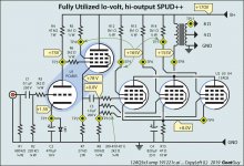
Nice.Here's an updated drawing.
I have annotated a couple of values with a greenish background, as they were totally wrong from version 1.0 of the schematic (my error, mea culpa.)
Note in particular that the R₁₅ cathode resistor needs to drop to 47 Ω from 100 (96) Ω. You could do this by putting 2 ea of the 96 Ω resistors in parallel. If you've got a bunch.
I was kind of worried about the 'kinkiness' of the pentode in the PCL805 in service as a cathode-follower. However, reading further, in that duty of service, the kinkiness doesn't matter. Doesn't contribute to appreciable signal distortion.
Also, other cosmetic fixes. And the LED. Etc.
-= GoatGuy ✓ =-
Actually, I'm using two 48Ohm resistors in series 😀
I am almost done. Just need to hook up the pentode.
You can draw schematics with Digi-keys' Scheme-it for free
Scheme-it | Free Online Schematic and Diagramming Tool | DigiKey Electronics
Scheme-it | Free Online Schematic and Diagramming Tool | DigiKey Electronics
You can draw schematics with Digi-keys' Scheme-it for free
Scheme-it | Free Online Schematic and Diagramming Tool | DigiKey Electronics
There you go!
Always listen to KodaBMX.
That's my advice.
Rarely wrong.
Often subtle.
Good DIY'er
GoatGuy
You can draw schematics with Digi-keys' Scheme-it for free
Scheme-it | Free Online Schematic and Diagramming Tool | DigiKey Electronics
Oh, nice! Thanks!
First power on, no sound ��Here's an updated drawing.
I have annotated a couple of values with a greenish background, as they were totally wrong from version 1.0 of the schematic (my error, mea culpa.)
Note in particular that the R₁₅ cathode resistor needs to drop to 47 Ω from 100 (96) Ω. You could do this by putting 2 ea of the 96 Ω resistors in parallel. If you've got a bunch.
I was kind of worried about the 'kinkiness' of the pentode in the PCL805 in service as a cathode-follower. However, reading further, in that duty of service, the kinkiness doesn't matter. Doesn't contribute to appreciable signal distortion.
Also, other cosmetic fixes. And the LED. Etc.
-= GoatGuy ✓ =-
Will check the wiring and test again.
Here's an updated drawing.
I have annotated a couple of values with a greenish background, as they were totally wrong from version 1.0 of the schematic (my error, mea culpa.)
Note in particular that the R₁₅ cathode resistor needs to drop to 47 Ω from 100 (96) Ω. You could do this by putting 2 ea of the 96 Ω resistors in parallel. If you've got a bunch.
I was kind of worried about the 'kinkiness' of the pentode in the PCL805 in service as a cathode-follower. However, reading further, in that duty of service, the kinkiness doesn't matter. Doesn't contribute to appreciable signal distortion.
Also, other cosmetic fixes. And the LED. Etc.
-= GoatGuy ✓ =-
Disappointing news:
It sounds basically the same as before.
My multimeter also died on me.
First power on, no sound ��
Will check the wiring and test again.
Well, that was fast.
HERE is the 'next version', with numbered test points, so we can
use the 'same language' when talking about measured values.
-= GoatGuy ✓ =-
Attachments
Last edited:
Well, that was fast.
HERE is the 'next version', with numbered test points, so we can
use the 'same language' when talking about measured values.
-= GoatGuy ✓ =-
I only have my Arduino-based multimeter to test voltage and it only goes up to 40V. I will test a few and tell you.
The no sound was because of pentode's anode being disconnected from the B+.
I only have my Arduino-based multimeter to test voltage and it only goes up to 40V. I will test a few and tell you.
The no sound was because of pentode's anode being disconnected from the B+.
Well, brother DIY'er, it is time to buy a proper multimeter. You need not spend more than $14 on one. I used a small — but quite satisfactory — $9.99 one purchased from the now defunct Radio Shack, some years ago. Took lil' flat 'coin' batteries. Did everything.
But a slightly better model would be ( Digital Multimeter Multi Tester Voltmeter Ammeter Ohmmeter with LCD Back Light 700819594799 | eBay )
Yuck. Ebay.
But eleven bucks.
You might notice that I also updated the capacitor annotations to actually have something other than 'C 1' for all caps!
🙄 Silly me.
-= GoatGuy ✓ =-
Triode cathode bias voltage: 1.577VWell, that was fast.
HERE is the 'next version', with numbered test points, so we can
use the 'same language' when talking about measured values.
-= GoatGuy ✓ =-
12AQ5 cathode resistor voltage: 4.080V
I think the problem is with the 12AQ5s as they're not drawing much current.
I might not buy the 6L6GC ($9) and save up for an old but highly accurate and awesome GW Instek GDM 450A.Well, brother DIY'er, it is time to buy a proper multimeter. You need not spend more than $14 on one. I used a small — but quite satisfactory — $9.99 one purchased from the now defunct Radio Shack, some years ago. Took lil' flat 'coin' batteries. Did everything.
But a slightly better model would be ( Digital Multimeter Multi Tester Voltmeter Ammeter Ohmmeter with LCD Back Light 700819594799 | eBay )
Yuck. Ebay.
But eleven bucks.
You might notice that I also updated the capacitor annotations to actually have something other than 'C 1' for all caps!
🙄 Silly me.
-= GoatGuy ✓ =-
www.esam.ir/item/16445703/مولتی-متر-INSTEK-GDM450Aتایوانی
It's about $30.
It will take 2 months to buy this though .-.
I'm 17 and don't get much monthly allowance ($25).
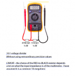
Will make a resistive divider to try and measure the high voltages with my DIY multimeter which has great accuracy (16bit ADC with calibrated 11.1M-1M resistive divider)!
PS... using a simple voltage divider, you can safely test higher voltages with your ~Arduino~ based multimeter. 2 resistors.
Here's the diagram
(ps - you do NOT need precision 'absolute', but relative value accuracy. It is an all-too-common fallacy to lust for absolute precision in measurement, when it is hardly ever required. I used to be 'in metrology'. )
Here's the diagram
(ps - you do NOT need precision 'absolute', but relative value accuracy. It is an all-too-common fallacy to lust for absolute precision in measurement, when it is hardly ever required. I used to be 'in metrology'. )
Attachments
Last edited:
Yes, i'm currently trying to measure the test points.PS... using a simple voltage divider, you can safely test higher voltages with your ~Arduino~ based multimeter. 2 resistors.
Here's the diagram
(ps - you do NOT need precision 'absolute', but relative value accuracy. It is an all-too-common fallacy to lust for absolute precision in measurement, when it is hardly ever required. I used to be 'in metrology'. )
You are right! But hey, everyone loves good accuracy 🙂
Because of the crude voltage divider, I have to round the numbers and stuff.Well, that was fast.
HERE is the 'next version', with numbered test points, so we can
use the 'same language' when talking about measured values.
-= GoatGuy ✓ =-
TP8-12AQ5s' anodes (transformer's primary through the coil): ~150V
TP2-Pentode's cathode: ~80V
TP10-12AQ5s': 0.00V
TP1-Triode's cathode: 1.577V
TP3-Triode's anode: ~80V
TP4-Pentode's screen: ~150V
TP5-6-8-12AQ5s' screen: ~140V
TP9-12AQ5s' cathode: ~4.2V
TP11-Transformer's output: 0.00V
Last edited:
Not sure this has been mentioned before, but I think you can't just put three tubes in parallel like this and expect them to share the load. There's always differences in gain and how much negative Vgk they need for a specific current.
The way it is now, the hottest tube will conduct all the current and cut off the others, and could even cause grid current on one or two. That will load down the preamp and cause massive distortion.
Pull out two of the three tubes and it probably gets a lot better.
Jan
The way it is now, the hottest tube will conduct all the current and cut off the others, and could even cause grid current on one or two. That will load down the preamp and cause massive distortion.
Pull out two of the three tubes and it probably gets a lot better.
Jan
That is true.Not sure this has been mentioned before, but I think you can't just put three tubes in parallel like this and expect them to share the load. There's always differences in gain and how much negative Vgk they need for a specific current.
The way it is now, the hottest tube will conduct all the current and cut off the others, and could even cause grid current on one or two. That will load down the preamp and cause massive distortion.
Pull out two of the three tubes and it probably gets a lot better.
Jan
I will test it and let you know.
The way to do this is to give each tube is own Rk and couple the grids via individual caps, so each tube can get to the autobias that fits its characteristics. You can then connect the anodes together if you wish.
Jan
Jan
Not sure this has been mentioned before, but I think you can't just put three tubes in parallel like this and expect them to share the load. There's always differences in gain and how much negative Vgk they need for a specific current.
The way it is now, the hottest tube will conduct all the current and cut off the others, and could even cause grid current on one or two. That will load down the preamp and cause massive distortion.
Pull out two of the three tubes and it probably gets a lot better.
Jan
Nope. Pulling out tubes just lowers the volume. The distortion is unaffected.
The way to do this is to give each tube is own Rk and couple the grids via individual caps, so each tube can get to the autobias that fits its characteristics. You can then connect the anodes together if you wish.
Jan
The problem is that I don't have three ~48Ohm high wattage resistors 🙁
- Home
- Amplifiers
- Tubes / Valves
- Help with 12AQ5 class A low gain and distortion