You need a coupling capacitor between the 'preamp' and 'finals' stage. But, once that's done, then the output tube G1 grids are 'floating'. They would be tied to ground via a 220 kΩ resistor. Given the 100 kΩ, and your likely desire to have frequency response down to 20 Hz, usingC (µF) = 1,000,000 / (2πFR)This would substantially open the dynamic range, also, of the amplifier.
F = 20 Hz
R = 100,000 Ω
C ≈ 0.1 µF at 350 V
The 96 Ω, 10 W cathode-bias resistor needs a bypass capacitor. FOR SURE, again to secure some reasonable output power.C = 1,000,000 / (2πFR)Now the output stage will produce some power, and it'll be cleaner.
F = 20 Hz
R = 96 Ω
C = 86 µF (call it 100 µF or 150 µF to be sure), at 35 V
Good luck.
-= GoatGuy ✓ =-
PS: one of the reasons I writeZ = 1,000,000 / (2πFC) … instead ofis because the (2πF) part is “officially” in charge of turning hertz Hz into radians-per-second, the mathematically proper statement of oscillatory rate. One could (as was popular in the Great Tube Days of the 1950s and 1960s) just remember to estimate
Z = 159,155/FC1,000,000 ÷ 2π ≈ 160,000and be done with it; the estimate is within 1% of accurate, which is by far, good enough. -= GoatGuy ✓ =-
Hi
Sorry I forgot to put 3 things in the schematic.
There is a 1uF cap between the pre-amp and the output amp. Also, there was an 820uF cap across the cathode resistor.
I have a 1MOhm resistor from the gates to ground (1 for all).
I was in a hurry and I forgot a few things.
Again, I am very sorry.
Last edited:
Hi
Sorry I forgot to put 3 things in the schematic.
There is a 1uF cap between the pre-amp and the output amp. Also, there was an 820uF cap across the cathode resistor.
I have a 1MOhm resistor from the gates to ground (1 for all).
I was in a hurry and I forgot a few things.
Again, I am very sorry.
A 100K grid leakage resistor decreases the volume and adds distortion.
You need some sort of grid leak there either way. Try maybe a 220k.
For each each?
One for the whole trio is fine. After the capacitor from the gain stage plate, before the individual grid stoppers. Anything from 100k-220k is fine, I'm not sure I would go higher.
(Max specified grid resistor is specified at 500k for cathode bias, so maybe a "perfect" value for three would be 100k-160k, but there's wiggle room here when run conservatively)
(Max specified grid resistor is specified at 500k for cathode bias, so maybe a "perfect" value for three would be 100k-160k, but there's wiggle room here when run conservatively)
Last edited:
One for the whole trio is fine. After the capacitor from the gain stage plate, before the individual grid stoppers. Anything from 100k-220k is fine, I'm not sure I would go higher.
Yeah. Will try and let you guys know shortly.
220k = worse than everOne for the whole trio is fine. After the capacitor from the gain stage plate, before the individual grid stoppers. Anything from 100k-220k is fine, I'm not sure I would go higher.
(Max specified grid resistor is specified at 500k for cathode bias, so maybe a "perfect" value for three would be 100k-160k, but there's wiggle room here when run conservatively)
I make a comment...
Then go off drawing...
And come back, and there are a ~lot more comments!~
Maybe this is getting close?
Then go off drawing...
And come back, and there are a ~lot more comments!~
Maybe this is getting close?
Attachments
Last edited:
220k = worse than ever
I just found an interesting and I think helpful behavior. When I disconnect the cathode from the resistor and then reconnect it, it starts off with a loud and super clear sound and after about two seconds, it fades away and continues with a muffled, distorted and low volume sound. Seems like a capacitive thing.
This still happens when I don't have the resistor bypass cap.
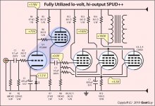
The circuit I drew utilizes the unused pentode section of the PCL805 to good effect: it significantly decreases the output impedance of the preamplifier section. And its already sitting there, doing nothing otherwise.
Just Saying,
-= GoatGuy ✓ =-
Just Saying,
-= GoatGuy ✓ =-
A question: is this an improved version of my amp or it's a tidy schematic of the current amp? (I think it's the improved version xD)I make a comment...
Then go off drawing...
And come back, and there are a ~lot more comments!~
Maybe this is getting close?
Are my 220Ohm screen stopper resistors too low?
Also, isn't the LED in backwards?
I didn't use the PCL805 pentode as I thought it would ruin things.
Yeah, nice.The circuit I drew utilizes the unused pentode section of the PCL805 to good effect: it significantly decreases the output impedance of the preamplifier section. And its already sitting there, doing nothing otherwise.
Just Saying,
-= GoatGuy ✓ =-
I'll start building it momentarily.
I make a comment...
Then go off drawing...
And come back, and there are a ~lot more comments!~
Maybe this is getting close?
Also, may I ask what kinda app you're using?
It would be a lot better if I could draw my schematics digitally.
A question: is this an improved version of my amp or it's a tidy schematic of the current amp? (I think it's the improved version xD)
Yes, my drawing was initially intended to tidy up yours. Then I decided to use the un-used pentode for an obvious improvement taking few components. Then I went 'about the datasheets', and revised some of your values for resistors and an input capacitor. Then I got out the calculator and put in some expected measurement voltage values.
Are my 220Ohm screen stopper resistors too low?
No, not too small. Better tho' is something between 1.0 kΩ and 4.7 kΩ.
Also, isn't the LED in backwards?
Embarrasing… yes, you're right. I'll flip it, and if we ever post another picture, it'll be right.
I didn't use the PCL805 pentode as I thought it would ruin things.
Nope, it'll make things better.
Just Saying,
-= GoatGuy ✓ =-
PS… re: drawing package
I'm using Adobe Illustrator (ancient CS–3 version). Been using Illustrator for over 20 years now. More like 25. But there are definitely other good vector schematic drawing packages. If you like fancy colors and custom symbols like I do and show in my schematics, a regular vector-drawing package is the way to go. Consider Sketch. If on the other hand, you want to invest in true schematic capture, which has the remarkable advantage of allowing simulation!, well … then one of the Eagle or other CAD packages is a better idea.
I'm rather old, so I still do all the resistor-and-capacitor-and-choke calculations in pencil, on scraps of paper … or if the circuit is complicated, I draw a deep breath and run the numbers in EXCEL, a darn-good spreadsheet. The really nice thing of spreadsheet calculations is that you can link results together, so changing one component — if you do a good job making things parametric — will result in all the other values being re-calculated almost instantly.
However, for a small circuit such as this one, I don't bother.
Paper, pencil, eraser, and my "basic excel spreadsheet" (which is just used to compute capacitance, inductance and resistance/wattage).
Yours,
-= GoatGuy ✓ =-
Last edited:
Yes, my drawing was initially intended to tidy up yours. Then I decided to use the un-used pentode for an obvious improvement taking few components. Then I went 'about the datasheets', and revised some of your values for resistors and an input capacitor. Then I got out the calculator and put in some expected measurement voltage values.
No, not too small. Better tho' is something between 1.0 kΩ and 4.7 kΩ.
Embarrasing… yes, you're right. I'll flip it, and if we ever post another picture, it'll be right.
Nope, it'll make things better.
Just Saying,
-= GoatGuy ✓ =-
Good call.
Is it necessary to change out the screen stoppers? They're in a really hard spot on the sockets.
We all make mistakes, eh? 😀
I've started changing and adding things.
Will let you know when I'm done with the mods.
Thanks man! 🙂
BTW what software are you using for drawing that nice schematic? Is this MS Paint?I make a comment...
Then go off drawing...
And come back, and there are a ~lot more comments!~
Maybe this is getting close?
edit: I just saw your comment answering my question. Thanks
Last edited:
Good call.
Is it necessary to change out the screen stoppers? NO
They're in a really hard spot on the sockets.
Thanks man! 🙂
You're welcome. Refresh your page… I added a footnote to the previous comment while there was still time to 'edit'. -= GoatGuy ✓ =-
BTW what software are you using for drawing that nice schematic? Is this MS Paint?
Thanks for noticing! I've edited the previous comment to include an answer to your question. -= GoatGuy ✓ =-
Yes, my drawing was initially intended to tidy up yours. Then I decided to use the un-used pentode for an obvious improvement taking few components. Then I went 'about the datasheets', and revised some of your values for resistors and an input capacitor. Then I got out the calculator and put in some expected measurement voltage values.
No, not too small. Better tho' is something between 1.0 kΩ and 4.7 kΩ.
Embarrasing… yes, you're right. I'll flip it, and if we ever post another picture, it'll be right.
Nope, it'll make things better.
Just Saying,
-= GoatGuy ✓ =-
PS… re: drawing package
I'm using Adobe Illustrator (ancient CS–3 version). Been using Illustrator for over 20 years now. More like 25. But there are definitely other good vector schematic drawing packages. If you like fancy colors and custom symbols like I do and show in my schematics, a regular vector-drawing package is the way to go. Consider Sketch. If on the other hand, you want to invest in true schematic capture, which has the remarkable advantage of allowing simulation!, well … then one of the Eagle or other CAD packages is a better idea.
I'm rather old, so I still do all the resistor-and-capacitor-and-choke calculations in pencil, on scraps of paper … or if the circuit is complicated, I draw a deep breath and run the numbers in EXCEL, a darn-good spreadsheet. The really nice thing of spreadsheet calculations is that you can link results together, so changing one component — if you do a good job making things parametric — will result in all the other values being re-calculated almost instantly.
However, for a small circuit such as this one, I don't bother.
Paper, pencil, eraser, and my "basic excel spreadsheet" (which is just used to compute capacitance, inductance and resistance/wattage).
Yours,
-= GoatGuy ✓ =-
Ah, I see.
I will try to find a free app as I barely even have money to buy tubes xD
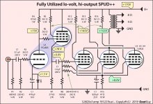
Here's an updated drawing.
I have annotated a couple of values with a greenish background, as they were totally wrong from version 1.0 of the schematic (my error, mea culpa.)
Note in particular that the R₁₅ cathode resistor needs to drop to 47 Ω from 100 (96) Ω. You could do this by putting 2 ea of the 96 Ω resistors in parallel. If you've got a bunch.
I was kind of worried about the 'kinkiness' of the pentode in the PCL805 in service as a cathode-follower. However, reading further, in that duty of service, the kinkiness doesn't matter. Doesn't contribute to appreciable signal distortion.
Also, other cosmetic fixes. And the LED. Etc.
-= GoatGuy ✓ =-
Attachments
- Home
- Amplifiers
- Tubes / Valves
- Help with 12AQ5 class A low gain and distortion