Don't just keep switching on and hoping... we have to find the problem by measurement and testing. Its quite possible there is a problem around Q18 and 19. Don't remove these transistors yet but you can do a basic resistive check (diode range) on them to see if they read obviously faulty.
Is the bulb still lit or not ? In the last post you say "used a different set of o/p transistrors... nothing I will try with a different set of drivers
What do you mean by nothing ? 🙂
1) Fit one pair of outputs and check that the 0.5 ohms for that pair are OK. Make sure that TR11 and D6 are linked out.
2) Remove R57 and R58 and briefly switch on. The bulb should not light.
3) Measure the DC voltage on L1. That is from 13 to 14. It should be low.
Report back what you find.
Don't just keep switching on and hoping... we have to find the problem by measurement and testing. Its quite possible there is a problem around Q18 and 19. Don't remove these transistors yet but you can do a basic resistive check (diode range) on them to see if they read obviously faulty.
Is the bulb still lit or not ? In the last post you say "used a different set of o/p transistrors... nothing I will try with a different set of drivers
What do you mean by nothing ? 🙂
1) Fit one pair of outputs and check that the 0.5 ohms for that pair are OK. Make sure that TR11 and D6 are linked out.
2) Remove R57 and R58 and briefly switch on. The bulb should not light.
3) Measure the DC voltage on L1. That is from 13 to 14. It should be low.
Report back what you find.
With "nothing" I meaned nothing changed after the interventions... probably a bad direct translation from italian 🙂
The 0.5ohm are fine, I removed R57-58 and the amp turn on but the DCV on L1 is high around 3V
3 volts is OK.
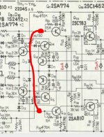
I'll have more time later hopefully but you can try refitting R57 and R58 and at the same time removing R36 and R37.
Also add another link as shown so that the bases' of both pre-drivers are linked.
The result should be similar. The bulb should be out and the voltage on L1 low.
If it is not then there is a problem around or with Q18 and 19
Attachments
3 volts is OK.
I'll have more time later hopefully but you can try refitting R57 and R58 and at the same time removing R36 and R37.
Also add another link as shown so that the bases' of both pre-drivers are linked.
The result should be similar. The bulb should be out and the voltage on L1 low.
If it is not then there is a problem around or with Q18 and 19
R57-58 in, R36-37 out... Without the link L1 3.2V, with the link -14V
Is the bulb still out ?
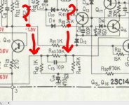
-14 volts doesn't sound right so one more quick check.
Leaving the amp as it is with R36/37 out and the new link in place measure the voltage on both sides of R43 (that's just to the left of Q19. You should still have the -14 volts on the right side. What is on the left side ?
Reason for that check is that if the output and driver and pre-driver stage is good then the output line (L1) is floating and R43 is the only component that could "put" a voltage on the output.
So if you have -14 volts on both sides of R43 then it indicates the output stage is OK.
If its not the same (within a volt or so) on both sides of R43 then remove Q18 and 19 and check them out of circuit. Compare them with a good NPN and PNP device checking across each junction each way.
And then wait 🙂
Attachments
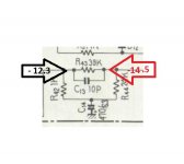
I suppose you meaned R34 not R43... Am I right?
EDIT: i tested both DCV at R34 -13V, at R43 150mv, L1 -14V
EDIT: i tested both DCV at R34 -13V, at R43 150mv, L1 -14V
Last edited:
Is the bulb still out ?
-14 volts doesn't sound right so one more quick check.
Leaving the amp as it is with R36/37 out and the new link in place measure the voltage on both sides of R43 (that's just to the left of Q19. You should still have the -14 volts on the right side. What is on the left side ?
Reason for that check is that if the output and driver and pre-driver stage is good then the output line (L1) is floating and R43 is the only component that could "put" a voltage on the output.
So if you have -14 volts on both sides of R43 then it indicates the output stage is OK.
If its not the same (within a volt or so) on both sides of R43 then remove Q18 and 19 and check them out of circuit. Compare them with a good NPN and PNP device checking across each junction each way.
And then wait 🙂
In the first place I misunderstood what you told me to do... I think I got it now
Attachments
Fit the two transistors as shown.
Check the resistors shown. Best to do that when Q18 and 19 are removed.
Then remove the last link we added but keep Q11 and D6 shorted. Refit R36 and 37 (and R57 and 58) and switch on.
Bulb should be out and voltage on L1 zero.
Check the resistors shown. Best to do that when Q18 and 19 are removed.
Then remove the last link we added but keep Q11 and D6 shorted. Refit R36 and 37 (and R57 and 58) and switch on.
Bulb should be out and voltage on L1 zero.
Attachments


Fit the two transistors as shown.
Check the resistors shown. Best to do that when Q18 and 19 are removed.
Then remove the last link we added but keep Q11 and D6 shorted. Refit R36 and 37 (and R57 and 58) and switch on.
Bulb should be out and voltage on L1 zero.
All the resistors are ok, I changed the transistors and now everything is fine. I regulate VR1 so that L1=0, bias is at 0. Now I will proceed with the other steps. I will remove the short on Q11 and regulate bias at 16mv as in the other channel
With VR2 at minimum bias is 95mv, I think I should put back R33 or should I try something different?
Last edited:
1- With VR2 at min, bias = 95mv
2- I inserted R33 back, bias = 85mv
3- I removed the 10K resistor over R32 (1.5K), bias = 45mv
4- I substituted R32 with 1.8K, bias = 0mv with VR2 at minimum (L1=0) 😀
Now I will put D11-12 back and insert 3 pairs of o/p transistors...
2- I inserted R33 back, bias = 85mv
3- I removed the 10K resistor over R32 (1.5K), bias = 45mv
4- I substituted R32 with 1.8K, bias = 0mv with VR2 at minimum (L1=0) 😀
Now I will put D11-12 back and insert 3 pairs of o/p transistors...
Great... so there was a problem with the pre-drivers.
We have to "fiddle" the components around Q11 to get the bias range correct. You say with R33 back the bias was 85mv.
You can lower the value of R31. Try putting a 10K across R31 but always use the bulb tester initially and remember on full mains the bias tended to be a bit higher so keep that in mind.
Great... so there was a problem with the pre-drivers.
We have to "fiddle" the components around Q11 to get the bias range correct. You say with R33 back the bias was 85mv.
You can lower the value of R31. Try putting a 10K across R31 but always use the bulb tester initially and remember on full mains the bias tended to be a bit higher so keep that in mind.
Ok.... I'm going to trow the amp out of the window

With bulb in, 3 pairs of transistors and 1.8K at R32 I was able to regulate L1 to 0 and bias to 16mv. I tested the amp with a speaker, perfect sound and bias less than 40mv. So I assembled back both channel and tested (with the bulb in), bias on that channel is now 42V 😱 how is that possible it was just perfect 5 minutes before and I didn't touch anything? (the other channel is fine)
EDIT: nevermind I got it
Last edited:
Where are you up to ? Your running on ahead again 🙂
The bulb will limit the current so much that the rails will collapse with both channels and all 3 pairs of outputs fitted.
The bulb will limit the current so much that the rails will collapse with both channels and all 3 pairs of outputs fitted.
I tested both channels at the same time with the bulb... YES finally it seem to work properly
But there's one strange thing, I tested the working channel with the bulb and the bias is 0.6mv (the last time I touched the bias on that channel was without the bulb and after 2 hours of music), so I used the same setting for the other channel. Now the final test without the bulb.... I keep my fingers crossed 🙂
But there's one strange thing, I tested the working channel with the bulb and the bias is 0.6mv (the last time I touched the bias on that channel was without the bulb and after 2 hours of music), so I used the same setting for the other channel. Now the final test without the bulb.... I keep my fingers crossed 🙂
So all is working 🙂
Keep a watch on the bias. Without actually experiencing first hand how it varies with temperature makes it more difficult. And keep feeling the heatsink too. Remember the lower the bias and the cooler and more reliable it will all be.
Test cautiously to begin with and keep monitoring.
Keep a watch on the bias. Without actually experiencing first hand how it varies with temperature makes it more difficult. And keep feeling the heatsink too. Remember the lower the bias and the cooler and more reliable it will all be.
Test cautiously to begin with and keep monitoring.
- Status
- Not open for further replies.
- Home
- Amplifiers
- Solid State
- Help repairing Pioneer M3