Hi, firstly let me introduce myself, my name is Giulio and I'm 27 years old. I'm new to this forum and I have little experience with audio equipment. I just builded a couple of tube amps and two DACs and I really enjoyed doing it.
For my next project I would like to repair my dad's old amp a Pioneer M3. For me is a chance to get some experience plus it could be a good birthday present for my dad.
Unfortunately I have no informations on what parts are broke, the only thing I know is that it was sended to pioneer for repairing it but they wanted too much money. At that time the amp wasn't a priority and it ended up in the basement
I managed to open the case, this is a first look at the inside
The first thing I noticed is the bad condition of the transformer, so I decided to remove it. During this operation I discovered that the transformer wasn't actually connected and all the cables are cutted
Looking at the bottom conditions I don't think they did a good job at pioneer, as you can see 3 out of 4 "foot" are lost and the metal case is really damaged. The only good thing is that luckily I found where all the transformer cables should be connected, so fixing this part shouldn't be difficult. You can see some of the cables in the next photo
In the above picture you can also see 3 fuses on the top right, I check them and they are all fine, hopefully it could be a good news.
Now my first question, how can I verify if the power transformer work? Should I just connect it to the 220 and check with a multimeter if the right volts come out from the secondaries (60, 47, 7.5) or there's something else I should do?
In the case the transformer is damaged and I need a replacement, how should I determine the VA required? (the only thing I know is that the amp is 340W)
The other parts that could be broke are the transistors, so I removed the left channel amp in order to check.
Front:
Back:
Amp pcb:
I checked with a multimeter all the resistors and diodes, everything is fine but I'm lost with the transistors... B, C, E, are evidentiated on the back, I tried to connect one probe to B and the other to C and E, then I tried the inverse. The problem is that I receive no value in all cases, the multimeter just "spark" and then go to zero after one second. What I'm doing wrong? Is it possible that all the transistors are broke?
Thanks in advance for the help and sorry for my bad english and my too basic electronic knowledge.
For my next project I would like to repair my dad's old amp a Pioneer M3. For me is a chance to get some experience plus it could be a good birthday present for my dad.
Unfortunately I have no informations on what parts are broke, the only thing I know is that it was sended to pioneer for repairing it but they wanted too much money. At that time the amp wasn't a priority and it ended up in the basement
I managed to open the case, this is a first look at the inside
An externally hosted image should be here but it was not working when we last tested it.
The first thing I noticed is the bad condition of the transformer, so I decided to remove it. During this operation I discovered that the transformer wasn't actually connected and all the cables are cutted
An externally hosted image should be here but it was not working when we last tested it.
Looking at the bottom conditions I don't think they did a good job at pioneer, as you can see 3 out of 4 "foot" are lost and the metal case is really damaged. The only good thing is that luckily I found where all the transformer cables should be connected, so fixing this part shouldn't be difficult. You can see some of the cables in the next photo
An externally hosted image should be here but it was not working when we last tested it.
In the above picture you can also see 3 fuses on the top right, I check them and they are all fine, hopefully it could be a good news.
Now my first question, how can I verify if the power transformer work? Should I just connect it to the 220 and check with a multimeter if the right volts come out from the secondaries (60, 47, 7.5) or there's something else I should do?
In the case the transformer is damaged and I need a replacement, how should I determine the VA required? (the only thing I know is that the amp is 340W)
The other parts that could be broke are the transistors, so I removed the left channel amp in order to check.
Front:
An externally hosted image should be here but it was not working when we last tested it.
Back:
An externally hosted image should be here but it was not working when we last tested it.
Amp pcb:
An externally hosted image should be here but it was not working when we last tested it.
I checked with a multimeter all the resistors and diodes, everything is fine but I'm lost with the transistors... B, C, E, are evidentiated on the back, I tried to connect one probe to B and the other to C and E, then I tried the inverse. The problem is that I receive no value in all cases, the multimeter just "spark" and then go to zero after one second. What I'm doing wrong? Is it possible that all the transistors are broke?
Thanks in advance for the help and sorry for my bad english and my too basic electronic knowledge.
If the meter sparks then it sounds like you are trying to test them with the amp on (which it must not be) or that there is residual charge on the rails from the PSU caps being charged.
This is an ambitious project to start with you have to realise that.
Power transistors almost always fail short circuit C to E
I would also advise against plugging in to the mains without some sort of current limiter. Search the forums for "bulb tester"
To even attempt this you need the full circuit diagram.
This is an ambitious project to start with
you have to realise that.Power transistors almost always fail short circuit C to E
I would also advise against plugging in to the mains without some sort of current limiter. Search the forums for "bulb tester"
To even attempt this you need the full circuit diagram.
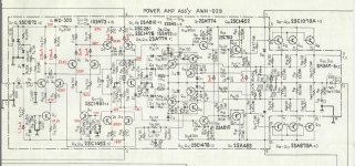
Someone has worked on that amp, poorly. The output transistors are all different types, suggesting that someone just put in whatever they had to hand. The original power transistors should be Toshiba. Whoever did that probably damaged the transformer too.
You need a schematic to get anywhere, fortunately a quick Google brings up this:
Pioneer M3 Exclusive Service Manual free download,schematics,datasheets,eeprom bins,pcb,repair info for test equipment and electronics
As for the transformer, the problem here is that the original has multiple windings. You're not going to find that "off the shelf", so you would have to have a custom transformer made.
If the meter sparks then it sounds like you are trying to test them with the amp on (which it must not be) or that there is residual charge on the rails from the PSU caps being charged.
This is an ambitious project to start with
Power transistors almost always fail short circuit C to E
I would also advise against plugging in to the mains without some sort of current limiter. Search the forums for "bulb tester"
To even attempt this you need the full circuit diagram.
I have the diagram but I can't post it since the file is too big.
Sorry probably spark isn't the righ word, what I meaned is that when I try to test the multimeter go to a number like 0.654 and then after a second go back to 0.000, so I could not determine if the transistor is working or not. By the way as you can see from the 5th picture I completely removed the trasistors from the amp for testing
I know is an hard project but the amp don't work and nobody except me really care about fixing it. So in the end even if I make some mistakes in the worse case I will just do some damages on something broke
If any "normal" transistor reads 0.00 or anything less than 0.5 ish between any pins then its faulty. Your DVM is actually passing a small current when testing devices and the reading is the volt drop at the meter probes. So 0.654 is actually 654 millivolts and spot on for a silicon junction.
Be under no illusions about working on something like this. You would also need a source of replacement or suitable equivalents for any faulty semiconductors.
Be under no illusions about working on something like this. You would also need a source of replacement or suitable equivalents for any faulty semiconductors.
Someone has worked on that amp, poorly. The output transistors are all different types, suggesting that someone just put in whatever they had to hand. The original power transistors should be Toshiba. Whoever did that probably damaged the transformer too.
You need a schematic to get anywhere, fortunately a quick Google brings up this:
Pioneer M3 Exclusive Service Manual free download,schematics,datasheets,eeprom bins,pcb,repair info for test equipment and electronics
As for the transformer, the problem here is that the original has multiple windings. You're not going to find that "off the shelf", so you would have to have a custom transformer made.
Thanks for the link, I know the custom transformer is the only solution and luckily there's a company close to where I live who can make it. But before I contact them I would like to test if this transformer is working. In any case I know the secondaries but what about the other characteristics of the transformer? should I look for a toroidal?
About the differents transistors, in my first post I skipped some details. The amp was sended to pioneer to be fixed (around half 80') they substitutes the transistors. After a month that it come back the amp broke again, It was sended back to pioneer for a second time but since they wanted more money to fix it, we didn't do it.
I can probably found in the diagram what the original transistors should be but there are chances to find a replacement nowadays?
Last edited:
Is this the one.
If you are really intent on having a go then we can come up with a plan to test and work on it (but not today
One thing is sure, I'm not in a hurry and I'm really intentioned to do this project
I know is difficult at that I can achieve poor results, but this don't scare me at all. Plus if everything go right I could end up with a complete vintage hifi, the pioneer C3 preamp is working right and I recently fixed the speakers (and I love them)
There is no way that amp was repaired by Pioneer, or any reputable service centre - a real repair centre would have used the correct parts, or at least some reasonable substitutes. The original transistors will now be obsolete and unobtainable, so you will have to make substitutes, assuming the amp is not so badly damaged that it is not worth saving.
Transformer - test by putting a 100W incandescent (an old filament type - NOT an "energy saving") bulb in SERIES with the primary winding. This will allow you to test the secondary windings with a multimeter set to AC Volts. You can see the organisation of the windings on top of the transformer, and the voltages you should get.
The next thing I would do, is to take both power amp modules out, reconnect the transformer, and test the power supply part. Leave the bulb in line with the primary winding to protect and indicate a fault. The schematic shows what voltages you should be getting at various terminals. If they don't match up, don't proceed any further. Your bulb should glow brightly at first but dim quickly as the power supply capacitors charge.
On that note, those power supply capacitors are huge. Get yourself a 10W power resistor, say 68-100 ohms. Attach some insulated probes to it. Use it across the capacitors whenever you have had the circuit energised to discharge them. Don't just short them with a screwdriver - it makes a loud bang, a big spark, and will ruin both your screwdriver and the capacitors.
Beware that each capacitor stores nearly 70V - that is 140V total, which can easily kill or seriously injure you.
There is no way that amp was repaired by Pioneer, or any reputable service centre - a real repair centre would have used the correct parts, or at least some reasonable substitutes. The original transistors will now be obsolete and unobtainable, so you will have to make substitutes, assuming the amp is not so badly damaged that it is not worth saving.
Transformer - test by putting a 100W incandescent (an old filament type - NOT an "energy saving") bulb in SERIES with the primary winding. This will allow you to test the secondary windings with a multimeter set to AC Volts. You can see the organisation of the windings on top of the transformer, and the voltages you should get.
The next thing I would do, is to take both power amp modules out, reconnect the transformer, and test the power supply part. Leave the bulb in line with the primary winding to protect and indicate a fault. The schematic shows what voltages you should be getting at various terminals. If they don't match up, don't proceed any further. Your bulb should glow brightly at first but dim quickly as the power supply capacitors charge.
On that note, those power supply capacitors are huge. Get yourself a 10W power resistor, say 68-100 ohms. Attach some insulated probes to it. Use it across the capacitors whenever you have had the circuit energised to discharge them. Don't just short them with a screwdriver - it makes a loud bang, a big spark, and will ruin both your screwdriver and the capacitors.
Beware that each capacitor stores nearly 70V - that is 140V total, which can easily kill or seriously injure you.
I cannot be 100% sure, the amp was repaired before I was even born and all the infos are from my mom memories. She remenber it was sended to pioneer repair centre but when I asked her if someone else also put his hands on it she can't denie or confirm.
The only thing sure is that the job wasn't professionaly done
- There are some miss screws in the case
- The transformer body is damaged as someone tried to pull out the transformer with a flat screw driver. (you can easily see it in the picture)
- The transistors are not original
I excuse myself if it look like I talked badly about pioneer, it wasn't my intention.
Thanks for the infos and for the security tips. I will test the transformer tomorrow and then I will post the results, for now I keep my fingers crossed
gde3,if I were you,I would send a PM to the member Sakis.He is an experienced repairer of vintage audio stuff and honest, as far as I can say.He repairs several hundrends of audio devices each year and he can obtain rare parts through his connection in Japan.Maybe he could undertake the repairment of your amplifier.
This is a very nice amp, probably as good as its big brother the M5 & M7.
Worth every penny and hour you waste on it to repair.
If you want to sell it let me know, I know someone who will pay a fair price for it, these pioneer classics amps are worth quite a lot of money for their age.
If you have the service manual, can I possibly get a copy of it ??
Worth every penny and hour you waste on it to repair.
If you want to sell it let me know, I know someone who will pay a fair price for it, these pioneer classics amps are worth quite a lot of money for their age.
If you have the service manual, can I possibly get a copy of it ??
Last edited:
Exclusive M3 repair
gde3,
try posting on audiokarma.org, as well. they have an exclusive Pioneer section with lots of experienced people there to help you out.
A service manual is available from
Main scan page
I could not get the SM from this site
Pioneer DV565a Service Manual free download,schematics,datasheets,eeprom bins,pcb,repair info for test equipment and electronics
If some of the O/P TO-3 trany's are gone you probably can get away with MJL21193/MJL21195's as subs. Need to check pinout of the TO-3's, but they are usually all the same.
Transformer secondary windings:
Red-white-red is the o/p trany supply, it is to be +/-66VDC, no load
Green-brown-green is the supply for the front end, +/-83VDC, then these voltages go through a few series pass trany ckts to produce a few secondary supply voltages.
You can send me a PM if you need further detailed help.
Good Luck
Rick
Correction:
MJL21193/MJL21195's (TO-263) should be MJ21193/MJ21195's(TO-3)
Suggest to test the transformer first using a ohmeter to check for opens, disconnected from the AC line, of course
Then if this is okay, check fuses, best to check DC voltages isolated from the loads & using either a variac or the dim bulb test as was previously suggested. Lets hope that the transformer is okay to start with, the rest can be fixed there after.
If the transformer is smoked, you can probably sub a SX-1050/1250 or similar transformer, if it fits and you can get it for 220/240VAC.
Last edited:
An externally hosted image should be here but it was not working when we last tested it.
I tested the transformer, I measured 7.85V for the 7.5V secondary, 68.6V for the 60V and 53.3V for the 47V. So I suppose the transformer is working right
Now the next step will be to remove the amp pcb and test the power supply, but for today I'm finish
By the way I found the original operating instructions and I made a pdf https://hotfile.com/dl/202580470/d652b14/M3_operating_instructions.pdf.html
That looks promising... all things are now possible
I can outline the next steps for you (if you wish) which consist of fitting the transformer back and disabling the output stage such that it can not draw excess current. It all has to be done very methodically with a lot of checks along the way to confirm all is well.
Powering of the amp (when that stage is reached) must be done with the bulb tester.
I can outline the next steps for you (if you wish
) which consist of fitting the transformer back and disabling the output stage such that it can not draw excess current. It all has to be done very methodically with a lot of checks along the way to confirm all is well.Powering of the amp (when that stage is reached) must be done with the bulb tester.
gde3,
try posting on audiokarma.org, as well. they have an exclusive Pioneer section with lots of experienced people there to help you out.
A service manual is available from
Main scan page
I could not get the SM from this site
Pioneer DV565a Service Manual free download,schematics,datasheets,eeprom bins,pcb,repair info for test equipment and electronics
If some of the O/P TO-3 trany's are gone you probably can get away with MJL21193/MJL21195's as subs. Need to check pinout of the TO-3's, but they are usually all the same.
Transformer secondary windings:
Red-white-red is the o/p trany supply, it is to be +/-66VDC, no load
Green-brown-green is the supply for the front end, +/-83VDC, then these voltages go through a few series pass trany ckts to produce a few secondary supply voltages.
You can send me a PM if you need further detailed help.
Good Luck
Rick
For the moment the registration to audiokarma is closed. I will check again in the near future. Thanks for the suggestion about the transformer but luckily mine seems to work
I removed both output stage from the chassis
Now there's a little problem about connecting the transformer.
Some of the cables are impossible to solder, in order to properly connect the transformer I have to completely disassemble the amp and put some new wires in. This will require some time and patience but at least I will clean all the dust
One more thing about the transformer, since the bottom is quite damaged I need to fix it or it will not fit in the slot. With a bench wise I should be able to realign the borders.
The second problem is the absence of 3 out of 4 nuts who are necessary for attaching the transformer to the case. This nuts were glued with a resin to the transformer, where I can find such resin?
An externally hosted image should be here but it was not working when we last tested it.
An externally hosted image should be here but it was not working when we last tested it.
Now there's a little problem about connecting the transformer.
Some of the cables are impossible to solder, in order to properly connect the transformer I have to completely disassemble the amp and put some new wires in. This will require some time and patience but at least I will clean all the dust
One more thing about the transformer, since the bottom is quite damaged I need to fix it or it will not fit in the slot. With a bench wise I should be able to realign the borders.
The second problem is the absence of 3 out of 4 nuts who are necessary for attaching the transformer to the case. This nuts were glued with a resin to the transformer, where I can find such resin?
- Status
- This old topic is closed. If you want to reopen this topic, contact a moderator using the "Report Post" button.
- Home
- Amplifiers
- Solid State
- Help repairing Pioneer M3