Just a couple of questions (sorry if some are really noobish)
- Using only 2 pairs of transistors instead of 3 can generate unbalance between the channels?
We do the same to the other channel and remove one pair of transistors in exactly the same way. When this amp was designed, high power and high voltage power transistors were not available and so paralleling devices was the only option.
Pioneer produced an amp (the A80. I owned one of those) that was also rated at 150 watts RMS and that used a single pair of outputs.
- I'm not interested to run this amp in class A, but if you guys have more informations on this topic I will be happy to read
Try the books by Douglas Self. "Audio Power Amplifier Design Handbook"
A 10 watts/8 ohm Class A amplifier would get hotter than yours 🙂
- The big caps are working right for the moment. Substitute them is something I should worry about in the future?
I think they will be fine tbh
- The amp has a subsonic filter (should work up to 8hz), on the manual it say to always leave it on since without there could be distorsion. Can someone please explain me a little further?
Subsonic filters are for use with vinyl records to stop the speaker cone moving to much. Dragging a stylus on a record generates huge amounts of really low frequencies which can damages speakers particularly with high power amps.
Orion and rumble - YouTube
- The preamp has six AC output. Is it better that I connect the amp to this power source or I keep amp and preamp separated? (in the first option a gnd cable is also connected between the two)
3 of this AC outlet are unswitched and rated up to 350W, 3 are switched 800W
If the preamp has an output designed to take the M3 then you can use it. But you have to be sure its suitable and mentioned in any instruction books as suitable. The numbers suggest otherwise. An amp of 150 watts RMS per channel will draw more than 350 watts at full power. So that rules the 350W feed out on that basis. The switched outputs are even more suspect because they will probably use the mains switch of the preamp to do the switching (unless high current relays are used ??) and given the high surge current of the power amp... you see the problem.
Some more general things you should check. Again be very careful what you do.
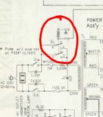
On the mains input there appears to be a relay (although its labelled as a switch). You need to confirm the operation of this is correct. This part of the circuit is a "slow start". If this wasn't working the amp would still actually work OK at lower levels but would be drawing all the power via the 3.3 ohm resistor.
So you need to confirm either by looking and watching or by listening that it clicks over correctly.
Also the speakers should have a delay of a couple of seconds (or more) when you switch on.
If at any time you decide to replace the other driver transistors with the MJE15032/3 pair then you must go through the same procedure for setting up. You would also have to alter the bias generator in the same way as on the other channel, removing R33 and fitting a 10K across R31.
Just as we did here,
http://www.diyaudio.com/forums/solid-state/233880-help-repairing-pioneer-m3-10.html#post3475065
You know the amp is rated at 150 Wrms. You might be interested to try this to see how much power you really need,
http://www.diyaudio.com/forums/mult...much-voltage-power-do-your-speakers-need.html
Attachments
I order a second set for both o/p and driver transistors, so in the future I could be prepared for any inconvenince 😉
The relay is working fine, I can easily ear it when it turn on and I can see it from the multimeter
JBL 4333 those are the speakers I will use with this amp. The specs are in the last page and you can see that they require 75W continuos sine wave, so the C3+M3 should be the perfect combination. By the way my goal for the future is bi-amp but that's a different story
Thanks a lot everyone for the precise answers on my doubts
it could be worth making sure that those terminal connectors are all tight, with connecting/disconnecting them a few times they may have expanded a bit and be loose. if you can slip back the plastic covers and give them a bit of a squeeze with pliers to make sure they're tight, it may help.
it could be worth making sure that those terminal connectors are all tight, with connecting/disconnecting them a few times they may have expanded a bit and be loose. if you can slip back the plastic covers and give them a bit of a squeeze with pliers to make sure they're tight, it may help.
I done that with all connections while assembling back the amp (I also cleaned each terminal from oxidation) but I'm going to open the amp and check it again
Unfortunately there's still a problem, I will open the amp and check the connections but the right channel is not working right (the one we have changed both drivers and o/p) it work with intermittence and a lot of distorsion, I hope the video could explain the situation
Difficult to say from the vidao but I see a lot of buttons under the VU meters, and these are presumably for signal routing, attenuation, subsonic filter etc. I would bet you have a contact problem somewhere in the switches or pots - while it's working give everything a 'wiggle', operate the switches, pots etc to see if anything changes.
My first guess would have been the speaker relay but I can see the left VY is not tracking the right one so the problem is not at the output - the input signal may not be getting to the amp board properly, I would check that before assuming the amp circuit is not working. If there was a real problem with the circuit it would likely result in the channel not working at all, DC offset etc, which would trip the protection circuits and you would not get a signal at all.
We do the same to the other channel and remove one pair of transistors in exactly the same way. When this amp was designed, high power and high voltage power transistors were not available and so paralleling devices was the only option.
Pioneer produced an amp (the A80. I owned one of those) that was also rated at 150 watts RMS and that used a single pair of outputs.
True but the A80 can't hold a candle to the M3 re reliability. Similar problem with for instance Sansui AU-D9 and D11 - one pair of superb Sanken outputs but no SOA for difficult loads.
Besides, there is no need to remove a pair at all. The only thing that changes with the 'extra' pair is slightly more input capacitance but with the drivers in this amp it's really no problem. However, there are considerable benefits. The output transistors provide a huge anmount of extra SOA compared to the originals. This is always welcome as the amp will be able to reliably drive anything, and in case of trouble it has a very high chance of surviving unscathed. But, more importantly, you get two additional benefits which are desirable from the performance standpoint.
Since the total idle current equals the sum of idle currents of all pairs, and the current per pair is de-facto fixed, 3 pairs will result in a 50% increase in idle current, and consequently slightly extend the area in which the amp works in class A, for the price of one pair and a little more idle heat.
Since there would be 3 pairs instead of 2, the maximum current for rated output is lowered by 1/3 per pair. This means the output stage will go less into the current gain drop-off area at higher powers or more difficult loads, so it will be more linear and more consistent in it's performance across many speaker types.
To sum it up, with bipolars if you can afford the outputs (and I think this should not be a consideration for an amp of this category!), use the same number of pairs. There are instances when a pair should be removed afetr exchanging parts for higher spec ones, but this mostly happens with MOSFET output stages.
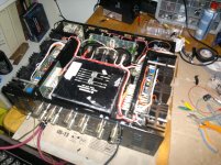
Now the amp work fine but I noticed a strange thing, the board with original transistors is really hot, can't touch it for more than 1-2 seconds, while the other is probably at 30°C
Video - TinyPic - Free Image Hosting, Photo Sharing & Video Hosting
Video - TinyPic - Free Image Hosting, Photo Sharing & Video Hosting
Something is not right if the board is that hot. Switch off while I read through everything you have posted.
Is it the board getting hot or the main heatsink ? If its the board can you tell approximately what area is hot.
Is it the board getting hot or the main heatsink ? If its the board can you tell approximately what area is hot.
The heatsink is hot, monstly the o/p transistors, the drivers seems a little colder
72 millivolts across 9 and 13.
That is to high. When the amp has cooled is the bias back to around 22 millivolts ?
And just confirm to be sure... this is the board with the original driver transistors. Yes ? And is the repaired channel with the new drivers behaving OK ?
That is to high. When the amp has cooled is the bias back to around 22 millivolts ?
And just confirm to be sure... this is the board with the original driver transistors. Yes ? And is the repaired channel with the new drivers behaving OK ?
- Status
- Not open for further replies.
- Home
- Amplifiers
- Solid State
- Help repairing Pioneer M3