This sounds more promising but we are not there yet 🙂
We have to work in stages on this. The final aim is to get the offset voltage (that's the DC voltage measure on L1 between points 13 and 14) to around zero. That's the easy bit.
The bias current (that we check by measuring the voltage between 13 and 9 needs to be adjustable to perhaps as high as 50 millivolts. There is a question mark over just what the intended bias current should be. I can't see it stated in the manual or the circuit but its not a problem... we will arrive at a suitable figure.
So you can achieve 2.4 millivolts with VR2 on minimum.
Can you now turn up VR2 and keep checking the voltage between 13 and 9. Don't go beyond about 50 millivolts (if it seems it will go that high). If it does adjust (but won't reach 50 millivolts) then note the maximum voltage achievable and then return VR2 back to minimum
I set the bias current to 0 and voltage between 13 and 9 to 50mv (it can go higher)This sounds more promising but we are not there yet 🙂
We have to work in stages on this. The final aim is to get the offset voltage (that's the DC voltage measure on L1 between points 13 and 14) to around zero. That's the easy bit.
The bias current (that we check by measuring the voltage between 13 and 9 needs to be adjustable to perhaps as high as 50 millivolts. There is a question mark over just what the intended bias current should be. I can't see it stated in the manual or the circuit but its not a problem... we will arrive at a suitable figure.
So you can achieve 2.4 millivolts with VR2 on minimum.
Can you now turn up VR2 and keep checking the voltage between 13 and 9. Don't go beyond about 50 millivolts (if it seems it will go that high). If it does adjust (but won't reach 50 millivolts) then note the maximum voltage achievable and then return VR2 back to minimum
This is the plan assuming all goes well with it...
We work on just this channel for now. (We know the other is basically OK).
Even with just 2.4 millivolts across 9 and 13 you should find that if you try the speaker again (with the bulb connecting the speaker for now) it should sound much better. The distortion should be gone.
That will be as far as we go for now. If the voltage across 13 and 9 doesn't come near 50 millivolts then we incrementally reduce the value of R32 probably trying a 1.2K next.
We always return VR2 to minimum after every change. That is really important.
When we are confident we have the right range of adjustment we then test using full mains (no bulb) and make sure the bias current is essentially unchanged.
We then go back to the bulb.
We then build the amp up further fitting the second pair of outputs and recheck.
If that's OK we move on to the third pair.
I set the bias current to 0 and voltage between 13 and 9 to 50mv (it can go higher)
You beat me to it 🙂
That's great. Turn it back down again to say around 10mv and recheck using the speaker.
This is the plan assuming all goes well with it...
We work on just this channel for now. (We know the other is basically OK).
Even with just 2.4 millivolts across 9 and 13 you should find that if you try the speaker again (with the bulb connecting the speaker for now) it should sound much better. The distortion should be gone.
That will be as far as we go for now. If the voltage across 13 and 9 doesn't come near 50 millivolts then we incrementally reduce the value of R32 probably trying a 1.2K next.
We always return VR2 to minimum after every change. That is really important.
When we are confident we have the right range of adjustment we then test using full mains (no bulb) and make sure the bias current is essentially unchanged.
We then go back to the bulb.
We then build the amp up further fitting the second pair of outputs and recheck.
If that's OK we move on to the third pair.
no distorsion on the speakers with VR2 at minimum
That's great, and that's probably a good time to leave it for tonight. Set VR2 to minimum again for safety.
I want to think some more on the bias range.
Let me just explain a little on what the bias current is.
Turning VR2 allows the output transistors to pass a little current all the time. This current minimises distortion.
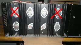
The practical problems are that this current generates heat. Lots of heat. A current of 100ma flowing through a transistor that has 66v across it generates 6.6 watts of heat. And you have twelveoutput transistors. That's 80 watts. A huge amount but it is a physically big amp although the heatsinks in the pictures aren't that huge tbh . This is why I would really like to know the recommended bias current.
Lets leave it there for now... its all basically working... and I'll see what I can come up with.
For reliability "lower is better" as the amp runs cooler. We also need to see how stable the bias is meaning "does it drift as the amp warms".
Excellent work getting this far 🙂
I want to think some more on the bias range.
Let me just explain a little on what the bias current is.
Turning VR2 allows the output transistors to pass a little current all the time. This current minimises distortion.
The practical problems are that this current generates heat. Lots of heat. A current of 100ma flowing through a transistor that has 66v across it generates 6.6 watts of heat. And you have twelveoutput transistors. That's 80 watts. A huge amount but it is a physically big amp although the heatsinks in the pictures aren't that huge tbh . This is why I would really like to know the recommended bias current.
Lets leave it there for now... its all basically working... and I'll see what I can come up with.
For reliability "lower is better" as the amp runs cooler. We also need to see how stable the bias is meaning "does it drift as the amp warms".
Excellent work getting this far 🙂
Mooly and gde3,
I am following this all the way, you are doing great guy's, I will celebrate with you soon !
I am following this all the way, you are doing great guy's, I will celebrate with you soon !
Mooly BTW, what would the bias drifting with 2mv+- have on an amp running on +- 56 v DC class AB. Will it be significant or something to worry about ?
That's great, and that's probably a good time to leave it for tonight. Set VR2 to minimum again for safety.
I want to think some more on the bias range.
Let me just explain a little on what the bias current is.
Turning VR2 allows the output transistors to pass a little current all the time. This current minimises distortion.
The practical problems are that this current generates heat. Lots of heat. A current of 100ma flowing through a transistor that has 66v across it generates 6.6 watts of heat. And you have twelveoutput transistors. That's 80 watts. A huge amount but it is a physically big amp although the heatsinks in the pictures aren't that huge tbh . This is why I would really like to know the recommended bias current.
Lets leave it there for now... its all basically working... and I'll see what I can come up with.
For reliability "lower is better" as the amp runs cooler. We also need to see how stable the bias is meaning "does it drift as the amp warms".
Excellent work getting this far 🙂
For what I know the amp broke for high temperature... the heatsink don't seem too big to me either but without heavy modifications there's no space in the case to fit a bigger heatsink. My best friend has an alluminium extrusion company, I will see if I find something usefull. By the way my idea is to fit 2 fans behind the case. I can mount them on the grill, is the simplest and less intrusive modification I can think about
Attachments

Last edited:
Mooly and gde3,
I am following this all the way, you are doing great guy's, I will celebrate with you soon !
Thanks Jan, It will still take a little bit of time but I'm really happy on how it's going on so far 🙂
Congrats on the success so far! Nice learning experience for me! Thanks!
I like the fan idea and it seems to keep my big old Pioneer A-717 nice and cool. Started doing it recently when I realized the heat slowly kills things, not that I have had any trouble with it except it recently works only with the Direct switch on (bypasses the tone controls). Switch is sealed so it's kind of strange. I usually only used it on Direct anyway so no big deal.
You can run 12V computer type fans on an old wallwart with less voltage for quieter running. Just make sure they have a good mA capacity and check temp of transformer.
Congrats on the success so far! Nice learning experience for me! Thanks!
I like the fan idea and it seems to keep my big old Pioneer A-717 nice and cool. Started doing it recently when I realized the heat slowly kills things, not that I have had any trouble with it except it recently works only with the Direct switch on (bypasses the tone controls). Switch is sealed so it's kind of strange. I usually only used it on Direct anyway so no big deal.
You can run 12V computer type fans on an old wallwart with less voltage for quieter running. Just make sure they have a good mA capacity and check temp of transformer.
Probably I will get two of those Noctua and a transformer with a simple potentiometer to regulate the rpm. For my experience this fans are perfect for low noise applications
That is correct, if you have a thermal sensor/switch mounted on the heatsinks, it could activate the fans if the temp gets above a certain temp.
Mooly BTW, what would the bias drifting with 2mv+- have on an amp running on +- 56 v DC class AB. Will it be significant or something to worry about ?
A bias drift of 2 mv (that's 2 millivolts measured across the 0.5 ohm emitter resistors) is negligible. Audibly, you won't tell any difference whether its running 10 or 200 milliamps, that's a range of 5 millivolts to 100 millivolts . So a drift of 2 millivolts on any set value is negligible.
Same for offset voltage. It should be zero but in practice even a value up to 100 millivolts either way draws only 12.5 milliamps through 8 ohms (about 1 milliwatt power dissipation in the speaker).
I've thought some more on the bias current, and a value around 50 milliamps seems closer to the ideal technically, given that the amp uses relatively high value emitter resistors. That would give a power dissipation of just over 3 watts per transistor (around 20 watts per channel).
Taking all this further, this is what I think might be a good idea.
Back in its day, this amp rated at 150 watts RMS needed the three pairs of output transistors to deliver that kind of output. Those originals (apart from voltage rating) are rated even less than old 2N3055/2955's
The devices we are using are far more highly specified and two pairs rather than three should be more than capable of meeting the full output required.
So here is the plan...
Still working on this channel only we fit just two pairs of outputs.
You adjust the bias to give 22 milivolts between 9 and 13
Leaving the amp on you monitor that voltage and make sure it is reasonably stable. It may go as high as 30 or 35 millivolts or so as the amp warms and then fall back down.
After say 30 minutes (and providing the voltage has been reasonably stable) you can then readjust the voltage back to 22 millivolts.
(Running two pairs of outputs rather than three has the huge benefit of reducing the heat produced).
If that test is all OK you then return VR2 back to minimum.
Remove the bulb tester so that the amp is on full mains.
Switch on and again reset VR2 following the above so that you have around 22 millivolts between 9 and 13 when the amp is full warmed.
At this point you can test this channel with a speaker. You can turn it up quite loud. Keep checking the heatsink temperature. As long as you can touch the transistors themselves for 4 or 5 seconds without burning yourself they are OK.
As it gets hotter we do another check.
Turn the volume right down (leave the speaker connected) and again check the voltage between 9 and 13. It should always be trying to fall back down to around the 22 millivolt level.
Attachments
I put back D11-12, I added two o/p transistors and I regulated the bias to 22mv. After 30 minutes the value stabilized at 24.2mv, during this time the value regularly increased
Then I set VR2 to minimum (bias 1.8mv) and turn off the amp...
I removed the bulb and connected the amp directly, turn on... nothing happen (not even the meter turn on) I inserted again the bulb and the amp don't start, the bulb don't even light on 😱
EDIT: the main fuse blow out, after checking I noticed that is rated 5A while it should be 6A. I hope the problem is just related to the old fuse, I will change all four just to be sure
Last edited:
The mains fuse needs to be a time delay or slow blow type and not a fast blow. It will say something like T6A or AS6A and not F6A
I would think the 1 amp fuses on the PSU board are time delay too.
I would think the 1 amp fuses on the PSU board are time delay too.
- Status
- Not open for further replies.
- Home
- Amplifiers
- Solid State
- Help repairing Pioneer M3