Two possibilities. One is that the "new" Vbe multiplier (TR11) isn't tracking the characteristics of the output stage correctly, or, the drivers are faulty or leaky in some way. Make sure TR11 is fitted the same as the other one and is in good thermal contact with the heatsink. I'm sure it is but check it.
I think the bottom line is that we need to rebuild this channel in the same way as the other using new drivers and doing the same resistor mods around TR11
I think the bottom line is that we need to rebuild this channel in the same way as the other using new drivers and doing the same resistor mods around TR11
As a test you could fit the MJE340 and MJE350 as temporary drivers to see if it all works OK.
That could be worth doing actually, to make sure that it really is all otherwise OK.
If you want to do that then we follow a definite plan as before using the bulb tester. Don't just fit them and switch on (and they are different pin outs to the MJE15032/3, the B and E are reversed)
That could be worth doing actually, to make sure that it really is all otherwise OK.
If you want to do that then we follow a definite plan as before using the bulb tester. Don't just fit them and switch on (and they are different pin outs to the MJE15032/3, the B and E are reversed)
TR11 seem fine, I also used a tension washer to keep it in place. I suppose you are right, maybe the drivers where not in good condition and the final test "kill" them.
I should receive the new transistor tomorrow or monday morning and proceed with mods
I should receive the new transistor tomorrow or monday morning and proceed with mods
from a closer inspection I noticed that R32 1.6K burn out, I checked and the value is 1.525ohm, I have one resistor of 1.490 ohm could I use it as substitute?
That's very strange. Yes you should be able to use 1.5K (K 🙂) Have you measured the 1.6K out of circuit.
Do you think that resistor has burnt today or burnt from some previous time. Given that other transistors had been fitted for TR11 in the past its possible it burnt during a previous repair. It should never ever see more than around 1.5 volts across it.
Do you think that resistor has burnt today or burnt from some previous time. Given that other transistors had been fitted for TR11 in the past its possible it burnt during a previous repair. It should never ever see more than around 1.5 volts across it.
It burn out during testing (not sure when if today or earlier) I carefully checked the boards while cleaning, I'm 100% positive it broked while I was working on the amp
You may have a problem with oscillation. First check that the idle current is OK when the heatsink is hot but there is no signal. Then, switch off the amp, wait a while for the capacitors to discharge (which is standard procedure, anyway), then have a look at the schematic. You will find a series combination of R and C across the speaker terminals and also across the output of the amp. Check that the resistor has not gone open, the capacitor has capacitance, and check that the connections are ok, especially the one to ground as this is usually routed separately.
We need to check this board by building it up and measuring along the way. The only way that resistor could burn is if TR11, B to E or D6 was open circuit allowing the resistor to see a high voltage.
If you can get parts locally I would obtain a couple of diodes such as 1N4148 or 1N914 (super common parts).
If you want to wait until the new parts come that's fine or we can test and work on this channel using what you have. Whatever suits 🙂 Its an easy and straightforward process.
If you can get parts locally I would obtain a couple of diodes such as 1N4148 or 1N914 (super common parts).
If you want to wait until the new parts come that's fine or we can test and work on this channel using what you have. Whatever suits 🙂 Its an easy and straightforward process.
You may have a problem with oscillation. First check that the idle current is OK when the heatsink is hot but there is no signal. Then, switch off the amp, wait a while for the capacitors to discharge (which is standard procedure, anyway), then have a look at the schematic. You will find a series combination of R and C across the speaker terminals and also across the output of the amp. Check that the resistor has not gone open, the capacitor has capacitance, and check that the connections are ok, especially the one to ground as this is usually routed separately.
That's a good point on oscillation, although I think this is a DC fault related to the original transistors.
The resistor and cap ilimzm refers to are C24 and R87
I been a little busy during the weekend and I didn't receive the parts...
By the way I spent some time testing the working channel. I added the 3rd pair of transistors, I set bias at 22mv and tested with the bulb for 30 minutes... everything fine. Then I tested without the bulb and the bias went as high as 100mv. I let the amp cool back and I tried a different thing, I regulate the bias without using the bulb. I set it at 22mv and I tested the amp for 30 minutes at an high volume, this time bias didn't pass 50mv and the amp stayed relatively cool 🙂
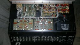
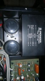
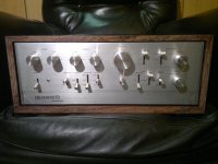
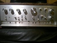
In the mean time I cleaned the preamp, there was some bad oxidation on the switches and potentiometers, now is like new. I hope you like the pictures 😎
By the way I spent some time testing the working channel. I added the 3rd pair of transistors, I set bias at 22mv and tested with the bulb for 30 minutes... everything fine. Then I tested without the bulb and the bias went as high as 100mv. I let the amp cool back and I tried a different thing, I regulate the bias without using the bulb. I set it at 22mv and I tested the amp for 30 minutes at an high volume, this time bias didn't pass 50mv and the amp stayed relatively cool 🙂
In the mean time I cleaned the preamp, there was some bad oxidation on the switches and potentiometers, now is like new. I hope you like the pictures 😎
Attachments

gde3, very nice to see. I am glad that you have accomplished this task and are on the road to restoring this fine vintage gear to fine working condition. If you do not mind, I'd love to add a pic of the pre-amp front and back panels to my collection.
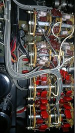
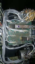
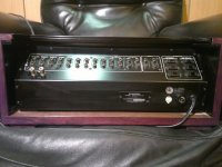
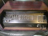
Amazed at the amount of wiring inside the unit!!
Thanks
Rick
Amazed at the amount of wiring inside the unit!!
Thanks
Rick
Last edited:
It looks great 🙂
As you are getting the hang of testing and adjusting the bias on the power amp, why don't you try going lower and seeing at what point you can hear when things start to sound worse.
I can't emphasise how important it is that the bias is stable such that it can never enter a runaway condition. Ideally time could be spent experimenting with the actual component values around TR11 and possibly modifying it slightly so that it tracks the output stage temperature better but we have to accept that isn't really a realistic proposition. I think the reason we have this "problem" is simply down to the modern semiconductors and the slightly different characteristic they have. So we have to work with what we have.
So try going a bit lower on the bias. Try 15 or even 10 mv. It all helps keep things cool and increases reliability.
It looks great 🙂
As you are getting the hang of testing and adjusting the bias on the power amp, why don't you try going lower and seeing at what point you can hear when things start to sound worse.
I can't emphasise how important it is that the bias is stable such that it can never enter a runaway condition. Ideally time could be spent experimenting with the actual component values around TR11 and possibly modifying it slightly so that it tracks the output stage temperature better but we have to accept that isn't really a realistic proposition. I think the reason we have this "problem" is simply down to the modern semiconductors and the slightly different characteristic they have. So we have to work with what we have.
So try going a bit lower on the bias. Try 15 or even 10 mv. It all helps keep things cool and increases reliability.
I think you got it exactly, when the amp temperature rise, bias go high, this is surely related to TR11 but I think I found an easy solution.
Instead of just setting the bias at the beggining I let the amp warm up, and regulate bias accordingly. With the attual setting bias don't pass 50mv even after 2 hours, while staying on average around 40mv. In this condition the amp temperature stayed in normal operating conditions (this is my main goal 😉)
Just to have a comparison, with the amp cool bias is now 16mv. I will check if there is any advantage to go even lower.
gde3, very nice to see. I am glad that you have accomplished this task and are on the road to restoring this fine vintage gear to fine working condition. If you do not mind, I'd love to add a pic of the pre-amp front and back panels to my collection.
Amazed at the amount of wiring inside the unit!!
Thanks
Rick
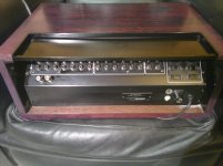
In that case I should add some more pictures of the finished work. Sorry for the quality but I only have a cellphone, I did my best
...The amount of wirng is incredible but how they are tied up is amazing, my compliments goes to whoever build it
Attachments
I hoped everything been easy with the second channel but I was wrong...
This is the situation, I removed D11-12, I removed R33, I shorted R1, I added a 10k resistor over R32 (1.5K insted of 1.6K) and I changed the drivers transistors.
At the moment there is some short circut I can't identify, if I turn on the amp the bulb stay on and some smoke came out from the 0.5ohm resistors. VR1 and VR2 at minimum, I don't know what to do 😕
I didn't think you had the parts yet. What have you fitted ?
Did the 0.5 ohms smoke with the bulb tester in place ?
You need to start (as you have done) but also with the shorting link across Q11 and D6.
Did the 0.5 ohms smoke with the bulb tester in place ?
You need to start (as you have done) but also with the shorting link across Q11 and D6.
I didn't think you had the parts yet. What have you fitted ?
Did the 0.5 ohms smoke with the bulb tester in place ?
You need to start (as you have done) but also with the shorting link across Q11 and D6.
I got the parts this morning but I could do it only now... yes they smoked with the bulb. By the way just to be safe I removed the other channel from the amp.
I put everything as in the other board except the link (I put the same drivers too), I hope that the problem is just the missing link
Double check all your work with the transistors. Make sure the correct types are fitted and that you haven't mixed up the NPN and PNP devices. Make sure they are all correctly fitted and that any needing insulation washers etc are in fact totally isolated from whatever they screw to. Check that with your meter.
Something is wrong, and more than the missing shorting link. The link forces (an otherwise good) output stage to draw no current.
Fit just one pair of outputs and also check the 0.5 ohms are OK for that pair.
Are you sure it was the 0.5 ohm that smoked and not anything nearby ? The bulb should limit the current to way below what would harm a 5 watt 0.5 ohm.
We'll have to carry this on tomorrow 🙂 Work slowly and carefully.
- Status
- Not open for further replies.
- Home
- Amplifiers
- Solid State
- Help repairing Pioneer M3